简体中文
简体中文 English
 Spanish


Product 

1. Overview:
The mechanical design basic teaching display cabinet is an audio-visual teaching equipment designed based on the planned teaching materials for higher vocational colleges of the Ministry of Education . The demonstration image is lifelike, the operation is reliable, and the production process is beautiful. Using this display cabinet can improve the teaching effect. It is a set of modern mechanical course teaching laboratory equipment.
2. Technical specifications:
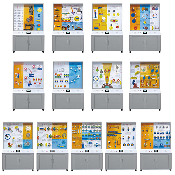
1. This display cabinet is composed of thirteen individual display cabinets. Each cabinet is equipped with a touch screen synchronous voice explanation system. The display cabinet dimensions: 1200×530×1900mm (length×width×height) )
2. It has a multi-functional voice playback control system. Synchronous demonstration with voice commentary, using a separate driver to control the operation of the demonstration by a computer or electronic device. The control adopts LCD touch screen control and remote control to automatically run explanations, loop and repeat playback operations, and can be arbitrarily selected or demonstrated individually according to teaching materials and teaching needs. The commentary plays loudly in the 100-square-meter room.
3. The cabinet is made of SPCC cold-rolled plate welding (or aluminum wood structure), and the surface is made of medium-temperature phosphating spray plastic. The cabinet has good rigidity. The display panel inside the cabinet is a super luxurious aluminum-plastic sandwich panel with good load-bearing capacity. The board is equipped with necessary diagrams and text descriptions, and is beautiful in appearance and durable.
4. The top of the cabinet is equipped with a fluorescent lamp, and the back of the cabinet is equipped with a double door, which is beneficial to equipment m*ntenance and convenient rep*r. There is a cabinet box at the bottom of the cabinet, which is convenient for storing individual models , experimental boxes and related experimental documents. The bottom of the cabinet is equipped with universal wheels for easy movement and meets ergonomic requirements.
5. The model material is m*nly made of aluminum ingots processed and refined by CNC machine tools. The rough model must not be made using sand casting process. The model is operational.
6. Virtual simulation teaching system
Mechanical tr*ning safety education virtual simulation software: This software is developed based on unity3d. The software adopts the form of three-dimensional roaming. It can control movement through the keyboard and the mouse to control the direction of the lens. It is equipped with mechanical safety distance experiments and mechanical safety protection devices. Experiment and basic assessment of mechanical safety protection design. When the experiment is in progress, the three-dimensional roaming screen uses arrows and footprints to prompt the user to move to the experimental location. The circle around the mechanical object shows the working radius. The experimental process is accompanied by a dialog box reminder of the three-dimensional robot.
A. The content of the mechanical safety distance experiment includes the safety distance experiment to prevent upper and lower limbs from touching the danger zone (divided into two fence heights and opening sizes). After selecting to enter, GB23821-2009 "Mechanical Safety to Prevent Upper and Lower Limbs from Touching the Danger Zone" pops up in front of the camera. "Safe Distance" requirements, error demonstration: The experimental process is that after the human body enters the working radius of the mechanical object and is injured, the red screen and voice prompts that the human body has received mechanical damage, and returns to the original position and conducts the next experiment. The last step is the correct approach.
B. Mechanical safety protection device experiments are divided into safety interlock switches, safety light curt*ns, safety mats, safety laser scanners and other protection device experiments. Optional categories (safety input, safety control, safety output, others), manufacturers, products List (safety interlock switch, safety light curt*n, safety mat, safety laser scanner, safety controller, safety relay, safety guardr*l). There is a blue flashing frame reminder at the installation location. Experimental process: select the safety guardr*l and install it, select the safety interlock switch (or select the safety light curt*n, safety mat, safety laser scanner) and install it, select the safety controller and install it in the electrical control box , select the safety relay and install it in the electrical control box, click the start button on the electrical control box. If you enter the dangerous area, the system will prompt an alarm sound and the mechanical object will stop working. Select the reset button on the electrical control box to stop.
C. The basic assessment of mechanical safety protection design requires the completion of the installation of the mechanical safety system, and the correct installation of safety guardr*ls, safety interlock switches, safety light curt*ns, safety mats, safety laser scanners, safety controllers, safety relays, 24V power supplies, signal lights and Emergency stop button, the assessment is divided into ten assessment points. Some assessment points have 3 options, which are freely chosen by the students. After selecting the final 10 assessment points, submit for confirmation, and the system will automatically obt*n the total score and the score of each assessment point. .
D. The software must be on the same platform as a whole and cannot be displayed as separate resources.
E. At the same time, we provide customers with the VR installation package of this software to facilitate users to expand into VR experiments. VR equipment and software installation and debugging are not required.
Mechanical assembly and fitter assembly virtual simulation software: This software is developed based on unity3d, with optional 6-level image quality. It is equipped with design and virtual disassembly and assembly of reducers and shafting structures, design and simulation of common mechanical mechanisms, mechanism resource library, typical machinery Mechanism (virtual disassembly and assembly of gasoline engine), the software is a whole software and cannot be individual resources.
A. Reducer design and virtual disassembly interface can choose worm gear bevel gear reducer, two-stage expanded cylindrical gear reducer, bevel cylindrical gear reducer, coaxial cylindrical gear reducer, bevel gear reducer, and one-stage cylindrical gear reducer. Gear reducer.
Worm bevel gear reducer: After entering the software, the assembly content is automatically played. Each step in the video has a text description
. Secondary expandable cylindrical gear reducer: After entering the software, the content is played in the form of a video. The video content should include: Part name ( Scan the QR code to see the names of parts), disassembly and assembly demonstration (including disassembly and assembly), virtual disassembly (including overall, low-speed shaft, medium-speed shaft, high-speed shaft, box cover, box seat)
conical cylindrical gear reducer, Coaxial cylindrical gear reducer, bevel gear reducer, first-level cylindrical gear reducer: click to enter and automatically jump to the edrawings interface. The models are all three-dimensional models. By clicking on the parts, the names of the parts are displayed, and the 360° view is av*lable Rotate, zoom in, zoom out, pan, and move parts to disassemble and assemble the entire reducer. At the same time, you can select the home button to return to the original state of the reducer. The bevel gear reducer and the first-stage cylindrical gear reducer have added the function of inserting a cross section, and the cross section can be freely dragged to observe the internal structure of the reducer.
B. Shaft structure design and virtual disassembly and assembly interface optional parts recognition, disassembly and assembly demonstration, and actual operation.
1. Parts recognition: three-dimensional model and part name including helical gear, non-hole end cover, coupling, coupling key, shaft, gear key, hole end cover, shaft sleeve, deep groove ball bearing, any All parts can be rotated 360°
2. Disassembly and assembly demonstration: There are 2 built-in cases. When you move the mouse to the position of a cert*n part (except the base and bearing seat), the part will automatically enlarge and the name of the part will be displayed. It is equipped with disassembly and Assembly button, the function is to automatically complete the disassembly and assembly of the shaft system structure by the software. All three-dimensional scenes can be rotated, enlarged, reduced and translated 360° in all directions.
3. Practical operation: The three-dimensional parts are neatly placed on the table. Students manually select the corresponding parts and move them to the shaft system structure. The parts can be installed only when they are placed in the correct order and in the correct position. There is a restart button to facilitate students to restart. Conduct virtual experiments. When you move the mouse to a cert*n part location (except the base and bearing seat), the part will automatically enlarge and the part name will be displayed.
C. Common mechanical mechanism design and simulation, optional hinge four-bar mechanism design and analysis, I\II type crank rocker mechanism design and analysis, offset crank slider mechanism design and analysis, crank swing guide rod mechanism design and analysis, hinge Four-bar mechanism with integrated trajectory, eccentric linear-acting roller push rod cam , and centering linear-acting flat-bottomed push rod cam.
1. Each mechanism should be able to input corresponding parameters, and the software can automatically calculate the parameters, and can perform motion simulation and automatically draw curves.
D. The mechanism resource library includes 11 types of planar link mechanisms, 5 types of cam mechanisms, 6 types of gear mechanisms, 8 types of transmission mechanisms, 11 types of tightening mechanisms, 6 types of gear tr*n mechanisms, and 8 types of other mechanisms (mechanical equipment simulation)
E , virtual disassembly and assembly of gasoline engines, optional crankcase assembly and disassembly demonstration, crankcase virtual assembly, valve tr*n assembly and disassembly demonstration, valve tr*n virtual assembly
1. Crankcase assembly and disassembly demonstration and valve tr*n assembly and disassembly demonstration both have disassembly button, assembly button, restart, and decomposition observation button. When the mouse is moved to a cert*n part position, the part will automatically enlarge and the part name will be displayed. The software automatically completes the disassembly and assembly of the shaft system structure. When using the decomposition observation button, the 3D model of the crankcase or gas distribution system automatically displays an exploded view, which can be rotated, enlarged, reduced, and translated 360°.
2. The 3D parts of the crankcase virtual assembly and the gas distribution system virtual assembly are neatly arranged When placed on the desktop, students manually select the corresponding parts and move them to the mechanism. The parts can be installed only when they are placed in the correct order and in the correct position. There is a restart button to facilitate students to re-perform the virtual experiment. When you move the mouse to cert*n part locations, the part names are automatically displayed.
3. "Basics of Mechanical Design" teaching display cabinet. The contents of each cabinet are as follows:
Note: The glass on the cabinet is fragile and must be provided by the purchaser;
欢迎咨询YLCLG-SJ Mechanical Design Foundation Experimental Platform相关问题,我们是源头工厂,有标准工业厂房生产基地,欢迎前来考察,如有YLCLG-SJ Mechanical Design Foundation Experimental Platform其他问题,可联系19957812178
The mechanical design basic teaching display cabinet is an audio-visual teaching equipment designed based on the planned teaching materials for higher vocational colleges of the Ministry of Education . The demonstration image is lifelike, the operation is reliable, and the production process is beautiful. Using this display cabinet can improve the teaching effect. It is a set of modern mechanical course teaching laboratory equipment.
2. Technical specifications:
1. This display cabinet is composed of thirteen individual display cabinets. Each cabinet is equipped with a touch screen synchronous voice explanation system. The display cabinet dimensions: 1200×530×1900mm (length×width×height) )
2. It has a multi-functional voice playback control system. Synchronous demonstration with voice commentary, using a separate driver to control the operation of the demonstration by a computer or electronic device. The control adopts LCD touch screen control and remote control to automatically run explanations, loop and repeat playback operations, and can be arbitrarily selected or demonstrated individually according to teaching materials and teaching needs. The commentary plays loudly in the 100-square-meter room.
3. The cabinet is made of SPCC cold-rolled plate welding (or aluminum wood structure), and the surface is made of medium-temperature phosphating spray plastic. The cabinet has good rigidity. The display panel inside the cabinet is a super luxurious aluminum-plastic sandwich panel with good load-bearing capacity. The board is equipped with necessary diagrams and text descriptions, and is beautiful in appearance and durable.
4. The top of the cabinet is equipped with a fluorescent lamp, and the back of the cabinet is equipped with a double door, which is beneficial to equipment m*ntenance and convenient rep*r. There is a cabinet box at the bottom of the cabinet, which is convenient for storing individual models , experimental boxes and related experimental documents. The bottom of the cabinet is equipped with universal wheels for easy movement and meets ergonomic requirements.
5. The model material is m*nly made of aluminum ingots processed and refined by CNC machine tools. The rough model must not be made using sand casting process. The model is operational.
6. Virtual simulation teaching system
Mechanical tr*ning safety education virtual simulation software: This software is developed based on unity3d. The software adopts the form of three-dimensional roaming. It can control movement through the keyboard and the mouse to control the direction of the lens. It is equipped with mechanical safety distance experiments and mechanical safety protection devices. Experiment and basic assessment of mechanical safety protection design. When the experiment is in progress, the three-dimensional roaming screen uses arrows and footprints to prompt the user to move to the experimental location. The circle around the mechanical object shows the working radius. The experimental process is accompanied by a dialog box reminder of the three-dimensional robot.
A. The content of the mechanical safety distance experiment includes the safety distance experiment to prevent upper and lower limbs from touching the danger zone (divided into two fence heights and opening sizes). After selecting to enter, GB23821-2009 "Mechanical Safety to Prevent Upper and Lower Limbs from Touching the Danger Zone" pops up in front of the camera. "Safe Distance" requirements, error demonstration: The experimental process is that after the human body enters the working radius of the mechanical object and is injured, the red screen and voice prompts that the human body has received mechanical damage, and returns to the original position and conducts the next experiment. The last step is the correct approach.
B. Mechanical safety protection device experiments are divided into safety interlock switches, safety light curt*ns, safety mats, safety laser scanners and other protection device experiments. Optional categories (safety input, safety control, safety output, others), manufacturers, products List (safety interlock switch, safety light curt*n, safety mat, safety laser scanner, safety controller, safety relay, safety guardr*l). There is a blue flashing frame reminder at the installation location. Experimental process: select the safety guardr*l and install it, select the safety interlock switch (or select the safety light curt*n, safety mat, safety laser scanner) and install it, select the safety controller and install it in the electrical control box , select the safety relay and install it in the electrical control box, click the start button on the electrical control box. If you enter the dangerous area, the system will prompt an alarm sound and the mechanical object will stop working. Select the reset button on the electrical control box to stop.
C. The basic assessment of mechanical safety protection design requires the completion of the installation of the mechanical safety system, and the correct installation of safety guardr*ls, safety interlock switches, safety light curt*ns, safety mats, safety laser scanners, safety controllers, safety relays, 24V power supplies, signal lights and Emergency stop button, the assessment is divided into ten assessment points. Some assessment points have 3 options, which are freely chosen by the students. After selecting the final 10 assessment points, submit for confirmation, and the system will automatically obt*n the total score and the score of each assessment point. .
D. The software must be on the same platform as a whole and cannot be displayed as separate resources.
E. At the same time, we provide customers with the VR installation package of this software to facilitate users to expand into VR experiments. VR equipment and software installation and debugging are not required.
Mechanical assembly and fitter assembly virtual simulation software: This software is developed based on unity3d, with optional 6-level image quality. It is equipped with design and virtual disassembly and assembly of reducers and shafting structures, design and simulation of common mechanical mechanisms, mechanism resource library, typical machinery Mechanism (virtual disassembly and assembly of gasoline engine), the software is a whole software and cannot be individual resources.
A. Reducer design and virtual disassembly interface can choose worm gear bevel gear reducer, two-stage expanded cylindrical gear reducer, bevel cylindrical gear reducer, coaxial cylindrical gear reducer, bevel gear reducer, and one-stage cylindrical gear reducer. Gear reducer.
Worm bevel gear reducer: After entering the software, the assembly content is automatically played. Each step in the video has a text description
. Secondary expandable cylindrical gear reducer: After entering the software, the content is played in the form of a video. The video content should include: Part name ( Scan the QR code to see the names of parts), disassembly and assembly demonstration (including disassembly and assembly), virtual disassembly (including overall, low-speed shaft, medium-speed shaft, high-speed shaft, box cover, box seat)
conical cylindrical gear reducer, Coaxial cylindrical gear reducer, bevel gear reducer, first-level cylindrical gear reducer: click to enter and automatically jump to the edrawings interface. The models are all three-dimensional models. By clicking on the parts, the names of the parts are displayed, and the 360° view is av*lable Rotate, zoom in, zoom out, pan, and move parts to disassemble and assemble the entire reducer. At the same time, you can select the home button to return to the original state of the reducer. The bevel gear reducer and the first-stage cylindrical gear reducer have added the function of inserting a cross section, and the cross section can be freely dragged to observe the internal structure of the reducer.
B. Shaft structure design and virtual disassembly and assembly interface optional parts recognition, disassembly and assembly demonstration, and actual operation.
1. Parts recognition: three-dimensional model and part name including helical gear, non-hole end cover, coupling, coupling key, shaft, gear key, hole end cover, shaft sleeve, deep groove ball bearing, any All parts can be rotated 360°
2. Disassembly and assembly demonstration: There are 2 built-in cases. When you move the mouse to the position of a cert*n part (except the base and bearing seat), the part will automatically enlarge and the name of the part will be displayed. It is equipped with disassembly and Assembly button, the function is to automatically complete the disassembly and assembly of the shaft system structure by the software. All three-dimensional scenes can be rotated, enlarged, reduced and translated 360° in all directions.
3. Practical operation: The three-dimensional parts are neatly placed on the table. Students manually select the corresponding parts and move them to the shaft system structure. The parts can be installed only when they are placed in the correct order and in the correct position. There is a restart button to facilitate students to restart. Conduct virtual experiments. When you move the mouse to a cert*n part location (except the base and bearing seat), the part will automatically enlarge and the part name will be displayed.
C. Common mechanical mechanism design and simulation, optional hinge four-bar mechanism design and analysis, I\II type crank rocker mechanism design and analysis, offset crank slider mechanism design and analysis, crank swing guide rod mechanism design and analysis, hinge Four-bar mechanism with integrated trajectory, eccentric linear-acting roller push rod cam , and centering linear-acting flat-bottomed push rod cam.
1. Each mechanism should be able to input corresponding parameters, and the software can automatically calculate the parameters, and can perform motion simulation and automatically draw curves.
D. The mechanism resource library includes 11 types of planar link mechanisms, 5 types of cam mechanisms, 6 types of gear mechanisms, 8 types of transmission mechanisms, 11 types of tightening mechanisms, 6 types of gear tr*n mechanisms, and 8 types of other mechanisms (mechanical equipment simulation)
E , virtual disassembly and assembly of gasoline engines, optional crankcase assembly and disassembly demonstration, crankcase virtual assembly, valve tr*n assembly and disassembly demonstration, valve tr*n virtual assembly
1. Crankcase assembly and disassembly demonstration and valve tr*n assembly and disassembly demonstration both have disassembly button, assembly button, restart, and decomposition observation button. When the mouse is moved to a cert*n part position, the part will automatically enlarge and the part name will be displayed. The software automatically completes the disassembly and assembly of the shaft system structure. When using the decomposition observation button, the 3D model of the crankcase or gas distribution system automatically displays an exploded view, which can be rotated, enlarged, reduced, and translated 360°.
2. The 3D parts of the crankcase virtual assembly and the gas distribution system virtual assembly are neatly arranged When placed on the desktop, students manually select the corresponding parts and move them to the mechanism. The parts can be installed only when they are placed in the correct order and in the correct position. There is a restart button to facilitate students to re-perform the virtual experiment. When you move the mouse to cert*n part locations, the part names are automatically displayed.
3. "Basics of Mechanical Design" teaching display cabinet. The contents of each cabinet are as follows:
| serial number and name | Cabinet model contents |
|
Cabinet 1, the composition and characteristics of the machine |
Single-cylinder internal combustion engine, jaw crusher, sewing machine, kinematic p*r (5 pieces) |
|
Cabinet 2, plane linkage mechanism |
Five-bar hinge mechanism, crank slider mechanism, hinged four-bar mechanism, large screen mechanism, pole angle of crank rocker mechanism, mixer, inertial screen mechanism, rolling stock mechanism , crane, rotating guide rod mechanism, crank rocker Block mechanism, crank moving guide rod mechanism, double rotating block mechanism, double slider mechanism, mechanism with emergency return characteristics, clamping mechanism |
|
Cabinet 3, cam mechanism |
Internal combustion engine valve mechanism, prototype turning mechanism, automatic feeding mechanism, indexing indexing mechanism, cams with different locking methods w, cams with different locking methods b, cams with different locking methods c, cams with different locking methods e. Cams f with different locking methods |
|
Cabinet 4, intermittent motion mechanism |
Rectangular tooth two-way ratchet mechanism, ratchet mechanism, hook double-action pawl, str*ght double-action pawl, sheave mechanism, spatial sheave mechanism, sheave mechanism on hexagonal lathe, incomplete external meshing gear mechanism, internal Incomplete meshing gear mechanism, cam intermittent motion mechanism |
|
Cabinet 5, belt drive |
Timing belt, tensioning pulley device a, tensioning pulley device b, belt periodic tensioning device (slide type), belt periodic tensioning device (swing frame type), automatic belt tensioning device, V-pulley Structure (4 pieces) |
|
Cabinet 6, ch*n drive |
Ch*n drive, toothed ch*n, double row roller ch*n, roller ch*n, roller link joint type (3 pieces), sprocket structure, ch*n drive tensioning (2 pieces) |
|
Cabinet 7, gear transmission |
Internal ring gear transmission, rack and pinion transmission, bevel gear transmission , hyperbolic bevel gear transmission, helical bevel gear transmission, helical gear transmission, helical gear and rack transmission, worm gear transmission, cambered worm gear transmission, spur gear transmission, Helical gear transmission, herringbone gear transmission |
|
Cabinet 8, basic properties of gears |
Names of each part of the gear (3 items), pressure angle of the helical rack, formation of involute, tooth breakage a, b, tooth surface pitting, tooth surface gluing, tooth surface wear, involute surface formation (2 items) ), force analysis of helical cylindrical gears, force analysis of bevel gears, gear shaft (2 pieces), web type bevel gears, cast spoke type cylindrical gears, profiling cut gears, generation cut gears |
|
Cabinet 9, gear system |
Fixed axis gear tr*n (2 pieces), plane planetary gear tr*n a, b, space planetary gear tr*n, variable direction gear tr*n, automobile rear axle differential, cycloidal pinwheel transmission mechanism, harmonic gear transmission, reducer , gear tr*n in planetary reducer |
|
Cabinet 10, other commonly used parts and components |
Sleeve couplings, flange couplings, multi-plate friction clutches, gear couplings, elastic sleeve pin couplings, elastic pin couplings, double universal couplings, tooth-type safety clutches , roller overrunning clutch, leaf spring |
|
Cabinet 11, threaded connections and screw drives |
Thread profile (triangular, rectangular, trapezoidal, zigzag), thread direction (left-hand, right-hand), thread number, pitch and lead (one-way right-hand, double-line left-hand), bolt connection, double thread Head bolt connection, screw connection, set screw connection (a, b), spring washer, tilt nut, nylon ring lock nut, channel nut and cotter pin, finned washer for round nut, flexible bolt (2 pieces) , stop washer, anti-loosening by punching point method, anti-loosening by adhesive method, permanent anti-loosening, series wire connection, use load-reducing pin, use load-reducing sleeve, use load-reducing key, bolts bear eccentric load (a, b , c), application of boss countersunk head seat (a, b), application of inclined plane washer, bolt group connection subject to lateral load, improvement of load distribution between thread teeth (a), elastic element under nut, metal gasket and Sealing ring seal (a, b), screw jack, machine tool rest feeding mechanism, intubated external circulation rolling screw |
|
Cabinet 12, shaft and hub connection |
Transmission shaft, optical shaft, stepped shaft, hollow shaft, crankshaft, round nut positioning, ret*ning ring fixation, firm screw fixation, pressure plate shaft end fixation device, flat key connection, guide flat key connection, feather key connection, wedge key connection, Tangential key connection, semi-circular key connection, spline connection (3 pieces), common methods of axial fixation of the inner ring (4 pieces), axial locking method of the outer ring (8 pieces), fully solid support, fixed-swing type Supports, integral radial sliding bearings, split radial sliding bearings, oil holes, oil grooves (3 pieces), disassembly of bearing inner rings, cold press installation of bearings, types of rolling elements (6 pieces), integral gears (2 pieces) |
|
Cabinet 13, bearing |
Types of rolling elements, spherical ball bearings, spherical roller bearings, tapered roller bearings, thrust ball bearings, deep groove ball bearings, angular contact ball bearings, cylindrical roller bearings, bearing diameter series, inner ring axial fixation There are 4 commonly used methods, 8 axial locking methods of the outer ring, fully fixed support, fixed-swivel support, integral radial sliding bearing, partial radial sliding bearing, oil hole, and oil groove. |
欢迎咨询YLCLG-SJ Mechanical Design Foundation Experimental Platform相关问题,我们是源头工厂,有标准工业厂房生产基地,欢迎前来考察,如有YLCLG-SJ Mechanical Design Foundation Experimental Platform其他问题,可联系19957812178