简体中文
简体中文 English
 Spanish


Product 

1. Product Overview
This tr*ning system is developed based on relevant national occupational standards and industry standards, combined with the mechanical and electromechanical major requirements of various vocational schools, and in accordance with the teaching and tr*ning requirements of vocational education. It is suitable for the " Hydraulic and Pneumatic Pressure " courses offered by vocational schools. Practical tr*ning and teaching of courses such as " Transmission Technology", "Hydraulic Transmission and Control", "Hydraulic and PLC Technology", " Pneumatic and PLC Technology". The practical tr*ning system integrates hydraulic, pneumatic, PLC electrical control and hydraulic simulation technologies. In addition to meeting the needs of professional tr*ning and teaching, it can also carry out skill assessments and vocational skills competitions. Through project-based tr*ning, it tr*ns students in the installation and debugging of hydraulic pump stations. , hydraulic system assembly and debugging, pneumatic system installation and debugging, electrical control technology, PLC application technology and hydraulic and pneumatic system operation and m*ntenance and other professional abilities.
2. Product Features
1. Close to the industrial site: the hydraulic pump station is designed in accordance with industrial standards and has additional assessment points; hydraulic and pneumatic components are from well-known domestic brands, and hydraulic proportional valves and superimposed valves are used to align with industry applications; the simulation device adopts industrial Typical control device, close to actual application in the industry.
2. Flexible system combination: Using modular structure design, modules can operate independently, or several modules can be combined into a comprehensive control system to facilitate equipment upgrades and expansions.
3. Strong comprehensiveness: The system integrates various industrial hydraulic and pneumatic components, relay control units, and PLC control units. It is a typical comprehensive tr*ning equipment integrating electro-hydraulic and pneumatic systems. It can not only meet the needs of basic hydraulic and pneumatic system tr*ning and teaching , you can also complete engineering tr*ning and vocational skills competitions.
4. Strong practicality: Set various practical work tasks according to relevant national occupational standards, industry standards and job requirements, with professional practice activities as the m*n line, and truly improve students' hands-on skills and employability through "learning by doing".
5. Low noise: The motor and pump shaft are integrally connected, the fuel tank and the tr*ning platform are placed separately, and high-pressure hoses are used to connect the vibration source and other mechanisms to prevent resonance, greatly reducing the noise and vibration generated by the pump station.
6. Strong safety: with current-type leakage protection and over-current protection to prevent misoperation from damaging the equipment; with phase sequence protection, when the phase is broken or the phase sequence is changed, the circuit power is cut off to prevent the motor from reversing; the system is equipped with Ultra-high voltage unloading protection function to avoid damage to components and ensure safety.
3. Technical parameters
1. Input power supply: three-phase four-wire (three-phase five-wire) ~ 380V ± 10% 50Hz;
2. Working environment: temperature -10℃ ~ 40℃, relative humidity ≤ 85% (25℃)
3. Device Capacity: ≤5.0kVA
4. Appearance dimensions: Tr*ning platform size: 2200mm×900mm×980mm
Double-pump hydraulic station size: 1400mm×700mm×900mm
5. Safety protection: With leakage voltage and leakage current protection, safety meets national standard
IV , System structure and composition
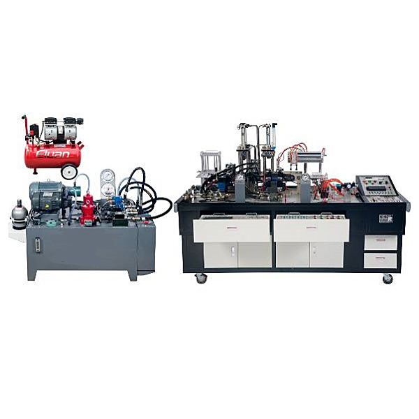
The system consists of three parts: a hydraulic and pneumatic comprehensive tr*ning platform, an industrial double-pump hydraulic station and a fully automatic steel rolling stamping simulation device.
The hydraulic and pneumatic comprehensive tr*ning platform m*nly consists of a tr*ning platform, hydraulic component module, superimposed valve tr*ning module, pneumatic component module, electrical control module, hydraulic and pneumatic simulation software, measurement and control instruments, assembly and adjustment tools, tr*ning accessories, and computer desk etc. composition.
The industrial double-pump hydraulic station uses two sets of hydraulic pump units, one of which is a high-pressure fixed piston pump unit and the other is a pressure-limiting variable vane pump unit. Each pump unit is equipped with a system pressure regulating component and a matching pump. Station control unit, the pumping station system is equipped with system pressure gauge, *r cooler, accumulator, liquid level control relay, oil temperature and level gauge, pressure pipeline filter, *r filter, etc.
The fully automatic steel rolling and stamping simulation device consists of a pneumatic loading tr*ning module, a transmission tr*ning module (hydraulic motor control), a steel rolling tr*ning module (double cylinder synchronization), a stamping tr*ning module, and a blanking tr*ning module (pneumatic manipulator). Through PLC control, the operation of independent sites can be completed, or a system can be formed to achieve linkage control.
5. Basic configuration
1. Basic configuration of hydraulic and pneumatic comprehensive tr*ning platform
2. Basic configuration of industrial double-pump hydraulic station
3. Basic configuration of fully automatic steel rolling stamping simulation device
6. Practical tr*ning project
Project 1 Installation and debugging of double-pump hydraulic station
1. Fixed pump-relief valve pressure regulating circuit
2. Variable pump-safety valve pressure regulating circuit
3. Double-pump parallel oil supply circuit
4. Hydraulic oil cooling circuit
5 .Reversing valve neutral pressure m*nt*ning circuit
Project 2 Basic hydraulic circuit construction and debugging
(1) Pressure regulating circuit
1. Simple pressure regulating circuit
2. Using reversing valve unloading circuit
3. Secondary pressure regulating circuit
4. Pressure reduction The pressure reducing circuit of the valve
5. The neutral unloading circuit of the reversing valve
6. The remote port unloading circuit of the pilot relief valve
7. The balancing circuit of the sequence valve
8. The accumulator pressure stabilizing circuit
9. The hydraulic cylinder loading circuit
(2) Speed regulating circuit
1. Throttle speed regulating circuit
2. Speed regulating circuit of speed regulating valve
3. Rapid movement circuit
4. Speed conversion circuit
(3) Direction control circuit
1. Reversing circuit using electromagnetic reversing valve
2 .Reversing circuit using manual valve
3. Locking circuit using hydraulically controlled one-way valve
4. Continuous reciprocating motion controlled by sequence valve
5. Neutral pressure m*nt*ning circuit of reversing valve
Project 3 Superimposed valve circuit construction and debugging
1. Pressure control circuit using superimposed valve
2. Speed control circuit using superimposed valve
3. Sequential action circuit using superimposed sequence valve
4. Pressure reducing circuit using superimposed pressure reducing valve
5. Use the provided superimposed valve to build a simulation device Action hydraulic system
Project 4 Proportional valve comprehensive tr*ning project
1. Hydraulic motor speed control circuit controlled by proportional speed control valve
2. PLC controlled proportional speed control valve speed control circuit
Project 5 Pneumatic circuit tr*ning project
1. *r source pressure control Circuit
2. *r source pressure delay output circuit
3. Working pressure control circuit
4. High and low pressure conversion circuit
5. Dual pressure drive circuit
6. Reversing circuit controlled by "OR" gate type shuttle valve
7. Double-acting cylinder reversing Loop
8. One-way/two-way speed regulation
loop of double-acting cylinder 9. Reciprocating action loop controlled by stroke valve
10. Sequential action loop
11. Position control loop using magnetic switch
Project 6 Construction and debugging of double-cylinder control loop of pneumatic loading device
Project 7: Construction and debugging of the pneumatic manipulator control circuit of the pneumatic blanking device
Project 8: Construction and debugging of the transmission device (hydraulic motor control) circuit
1. Use the solenoid valve to control the forward and reverse circuit of the motor
2. Use the solenoid valve neutral function to realize motor floating Loop
3. Motor speed regulating circuit using throttling speed regulation.
Project 9: Use superimposed valves to build the hydraulic system of the simulated m*n machine (press, combined machine tool, etc.) and complete the debugging
project 10. Simulated rolling mill (double cylinder synchronization-mechanical synchronization) circuit construction and debugging
1. Hydraulic cylinder multi-point position control system using displacement sensor
2. Double-cylinder mechanical synchronous control loop
Project 11 Double-cylinder synchronous loop
1. Double-cylinder synchronous loop controlled by speed regulating valve
2. Double-cylinder synchronous loop controlled by throttle valve Cylinder synchronization circuit
Project 12 Hydraulic and pneumatic simulation teaching and tr*ning project
1. Introduction and working principle of hydraulic transmission
2. Composition and functional simulation of hydraulic system
3. Operation and simulation of hydraulic circuit
4. Design and simulation of hydraulic circuit
5. Pneumatic pressure Introduction to transmission and simulation of working principle
6. Composition and functional simulation of pneumatic transmission
7. Operation and simulation of pneumatic circuit
欢迎咨询Ylyy-ZDZ Hydraulic Pneumatic Comprehensive Competition Experimental Platform相关问题,我们是源头工厂,有标准工业厂房生产基地,欢迎前来考察,如有Ylyy-ZDZ Hydraulic Pneumatic Comprehensive Competition Experimental Platform其他问题,可联系19957812178
This tr*ning system is developed based on relevant national occupational standards and industry standards, combined with the mechanical and electromechanical major requirements of various vocational schools, and in accordance with the teaching and tr*ning requirements of vocational education. It is suitable for the " Hydraulic and Pneumatic Pressure " courses offered by vocational schools. Practical tr*ning and teaching of courses such as " Transmission Technology", "Hydraulic Transmission and Control", "Hydraulic and PLC Technology", " Pneumatic and PLC Technology". The practical tr*ning system integrates hydraulic, pneumatic, PLC electrical control and hydraulic simulation technologies. In addition to meeting the needs of professional tr*ning and teaching, it can also carry out skill assessments and vocational skills competitions. Through project-based tr*ning, it tr*ns students in the installation and debugging of hydraulic pump stations. , hydraulic system assembly and debugging, pneumatic system installation and debugging, electrical control technology, PLC application technology and hydraulic and pneumatic system operation and m*ntenance and other professional abilities.
2. Product Features
1. Close to the industrial site: the hydraulic pump station is designed in accordance with industrial standards and has additional assessment points; hydraulic and pneumatic components are from well-known domestic brands, and hydraulic proportional valves and superimposed valves are used to align with industry applications; the simulation device adopts industrial Typical control device, close to actual application in the industry.
2. Flexible system combination: Using modular structure design, modules can operate independently, or several modules can be combined into a comprehensive control system to facilitate equipment upgrades and expansions.
3. Strong comprehensiveness: The system integrates various industrial hydraulic and pneumatic components, relay control units, and PLC control units. It is a typical comprehensive tr*ning equipment integrating electro-hydraulic and pneumatic systems. It can not only meet the needs of basic hydraulic and pneumatic system tr*ning and teaching , you can also complete engineering tr*ning and vocational skills competitions.
4. Strong practicality: Set various practical work tasks according to relevant national occupational standards, industry standards and job requirements, with professional practice activities as the m*n line, and truly improve students' hands-on skills and employability through "learning by doing".
5. Low noise: The motor and pump shaft are integrally connected, the fuel tank and the tr*ning platform are placed separately, and high-pressure hoses are used to connect the vibration source and other mechanisms to prevent resonance, greatly reducing the noise and vibration generated by the pump station.
6. Strong safety: with current-type leakage protection and over-current protection to prevent misoperation from damaging the equipment; with phase sequence protection, when the phase is broken or the phase sequence is changed, the circuit power is cut off to prevent the motor from reversing; the system is equipped with Ultra-high voltage unloading protection function to avoid damage to components and ensure safety.
3. Technical parameters
1. Input power supply: three-phase four-wire (three-phase five-wire) ~ 380V ± 10% 50Hz;
2. Working environment: temperature -10℃ ~ 40℃, relative humidity ≤ 85% (25℃)
3. Device Capacity: ≤5.0kVA
4. Appearance dimensions: Tr*ning platform size: 2200mm×900mm×980mm
Double-pump hydraulic station size: 1400mm×700mm×900mm
5. Safety protection: With leakage voltage and leakage current protection, safety meets national standard
IV , System structure and composition
The system consists of three parts: a hydraulic and pneumatic comprehensive tr*ning platform, an industrial double-pump hydraulic station and a fully automatic steel rolling stamping simulation device.
The hydraulic and pneumatic comprehensive tr*ning platform m*nly consists of a tr*ning platform, hydraulic component module, superimposed valve tr*ning module, pneumatic component module, electrical control module, hydraulic and pneumatic simulation software, measurement and control instruments, assembly and adjustment tools, tr*ning accessories, and computer desk etc. composition.
The industrial double-pump hydraulic station uses two sets of hydraulic pump units, one of which is a high-pressure fixed piston pump unit and the other is a pressure-limiting variable vane pump unit. Each pump unit is equipped with a system pressure regulating component and a matching pump. Station control unit, the pumping station system is equipped with system pressure gauge, *r cooler, accumulator, liquid level control relay, oil temperature and level gauge, pressure pipeline filter, *r filter, etc.
The fully automatic steel rolling and stamping simulation device consists of a pneumatic loading tr*ning module, a transmission tr*ning module (hydraulic motor control), a steel rolling tr*ning module (double cylinder synchronization), a stamping tr*ning module, and a blanking tr*ning module (pneumatic manipulator). Through PLC control, the operation of independent sites can be completed, or a system can be formed to achieve linkage control.
5. Basic configuration
1. Basic configuration of hydraulic and pneumatic comprehensive tr*ning platform
| serial number | Practical tr*ning module name | M*n configuration | quantity | Remark | |
| 1 | Basic tr*ning module | Tr*ning platform | The platform adopts an iron double-layer matte dense spray-p*nted structure and is equipped with electrical control components, storage cabinets for tr*ning components, and tool drawers. There are 4 universal wheels installed at the bottom for easy movement and layout. Size: 2200mm×900mm×980mm | 1 set | |
| 2 | *r compressor | Nominal volume 24L, rated flow: 116L/min, rated output *r pressure 1MPa | 1 set | ||
| 3 | Supporting tools | Electrician tool set includes digital multimeter, wire strippers, needle nose pliers, diagonal pliers, screwdriver, tweezers, scissors, soldering iron, soldering iron stand, soldering wire, etc.; Allen wrench (nine-piece set), Allen wrench (4mm ) 1 set, 1 adjustable wrench (0-150mm), 1 adjustable wrench (0-250mm), 1 adjustable wrench (0-300mm), 2 double open end wrenches. | 1 set | ||
| 4 | Tr*ning accessories | 24 industrial hydraulic hoses (including quick connectors at both ends); 20 meters of *r pipe, 10 T-shaped tees (APE6), 10 pipe plugs (APE6); 1 pack of special tr*ning wires; instruction manual and tr*ning guide; Software CD (including PLC programming software and PLC program); fuses and other wearing parts. | 1 set | ||
| 5 | Hydraulic and pneumatic transmission simulation tr*ning software | This software uses graphics, text, animation, simulation and other interactive animation methods to demonstrate the comprehensive tr*ning system of hydraulic and pneumatic transmission, simulates the working process of the fully automatic steel rolling stamping line, and expl*ns the m*n teaching of the entire hydraulic and pneumatic course. The content includes basic definitions and principles of components to internal structure animations, and from theoretical hydraulic and pneumatic circuits to the application of actual hydraulic and pneumatic systems. This software combines the functions, structures, and functions of each component of currently commonly used hydraulic and pneumatic systems to comprehensively dissect the working principles and processes of hydraulic and pneumatic systems. | 1 set | ||
| 6 | Electrical control module | power control unit | The power control unit is composed of a total power supply control and protection unit, a power supply voltage indication unit, a system start/stop control unit, and a system power output unit. | 1 set | |
| 7 |
DW-01 control button module |
The button module is equipped with 5 illuminated reset button switches, 5 illuminated self-locking button switches, 1 emergency stop switch, 1 two-position rotary switch, 1 three-position rotary switch, 1 buzzer, and all contacts of the above devices. All points are led to the panel to facilitate the connection of the control loop. | 1 set | ||
| 8 |
DW-02B Mitsubishi host module |
Using Mitsubishi's third generation 3U series host, FX3U-32MR 16-point input/16-point relay output, plus analog combination modules 4AD, 2DA, 4 inputs, 2 outputs. | 1 set | ||
| 9 |
DW-03 relay control module |
It is equipped with 8 DC 24V relays and 1 DC 24V time relay. All contacts are led to the panel to facilitate the connection of the control circuit. All switch value (including coil) terminals are led to the panel, and there are corresponding indicator lights when the coil is powered. | 1 set | ||
| 10 | DW-04 proportional speed valve control module | Power supply voltage: DC 24V±10%; power: 50W; control voltage: ±9V±2%; load resistance: 10Ω; maximum output current: 2200mA; oscillation frequency: 2.5kHz, etc. | 1 set | ||
| 11 | Measurement and control instruments | Shock resistant pressure gauge | YN-60ZQ/10MPa measuring range 0-10MPa, built-in methyl silicone oil | 2 | |
| 12 | turbine flow sensor | LGWY-6 | 1 | ||
| 13 | Smart measuring instrument | The smart instrument adopts LED digital display, and the internal control adopts advanced artificial intelligence adjustment (*) algorithm and has self-tuning (AT) function. | 1 | ||
| 14 | Hydraulic component module | Double acting hydraulic cylinder | Stroke 200mm | 2 | |
| 15 | Two-position three-way solenoid directional valve | 3WE6A61B/CG24N9Z5L | 2 | ||
| 16 | Two-position four-way solenoid directional valve | 4WE6C61B/CG24N9Z5L | 1 | ||
| 17 | One-way valve | RVP8 | 1 | ||
| 18 | Hydraulic control check valve | SV10PA2 | 2 | ||
| 19 | One-way throttle valve | DRVP8-1-10B/ | 2 | ||
| 20 | Two-way flow valve (speed regulating valve) | 2FRM5-31B/15QB | 2 | ||
| twenty one | Direct acting relief valve | DBDH6P10B/100 | 1 | ||
| twenty two | Direct acting sequence valve | DZ6DP1-5X/75 | 1 | ||
| twenty three | Direct acting pressure reducing valve | DR6DP1-5X/75YM | 1 | ||
| twenty four | pressure relay | HED4OP15B/100Z14L24 | 2 | ||
| 25 | Proportional speed regulating valve | 2FRE6B-20B/10QR | 1 | ||
| 26 | branch valve | 2 tees and 2 crosses, 45# steel surface nickel plated | 1 set | ||
| 27 | Plate valve base | The surface of 45# steel is nickel-plated, and the back of the valve adopts a spring buckle design. The oil inlet and outlet on the front of the valve plate are equipped with anti-leakage quick connectors, which are led out from the front. | 1 set | ||
| 28 | Stacking valve tr*ning module | Stacked relief valve | MBP-01-C-30 | 1 | |
| 29 | Stacked relief valve | MBB-01-C-30 | 1 | ||
| 30 | Stacked pressure reducing valve | MRP-01-B-30 | 1 | ||
| 31 | Stacked sequence valve | MHP-01-C-30 | 1 | ||
| 32 | Superposition pressure switch | MJCS-02-A-2-DC24 | 1 | ||
| 33 | Superposition pressure switch | MJCS-02-B-2-DC24 | 1 | ||
| 34 | Superimposed one-way throttle valve | MSA-01-X-10 | 1 | ||
| 35 | Superimposed one-way throttle valve | MSB-01-Y-10 | 1 | ||
| 36 | Stacked hydraulic control check valve | MPW-01-2-40 | 1 | ||
| 37 | Three-position four-way solenoid directional valve | DSG-01-3C2-D24-N1-50 (O type) | 1 | ||
| 38 | Three-position four-way solenoid directional valve | DSG-01-3C4-D24-N1-50 (Y type) | 1 | ||
| 39 | Three-position four-way solenoid directional valve | DSG-01-3C9-D24-N1-50 (P type) | 1 | ||
| 40 | Solenoid directional valve with emergency handle | DSG-01-3C3-DC24V-CA-N1 (H type) or HD-4WEM6H-7X/CG24N9 Z5L | 1 | ||
| 41 | Stacked valve double group basic valve plate | 45# steel surface nickel plating treatment | 1 | ||
| 42 |
Stacked electromagnetic one-way throttle valve |
FMS-G0-02A(24V) | 1 | ||
| 43 | Stacked valve three sets of basic valve plates | 45# steel surface nickel plating treatment | 1 | ||
| 44 | Stacked valve top plate | 45# steel surface nickel plating treatment | 2 | ||
| 45 | Stacked valve pressure gauge connection plate | 45# steel surface nickel plating treatment | 2 | ||
| 46 | Pneumatic component module | Double acting cylinder |
MAL-CA-32×125-S-LB (including magnetic switch and strap) |
2 | |
| 47 | Pneumatic triplex | AC2000-08 | 1 | ||
| 48 | Pressure regulating valve (with pressure gauge) | SR200-08 | 2 | ||
| 49 | Single solenoid controlled two-position three-way valve | 3V210-08NC/DC24V | 1 | ||
| 50 | 3V210-08NO/DC24V | 1 | |||
| 51 | Single solenoid controlled two-position five-way valve | 4V210-08/DC24V | 3 | ||
| 52 | Double electronically controlled two-position five-way valve | 4V220-08/DC24V | 2 | ||
| 53 | Three-position five-way solenoid directional valve | 4V230C-08/DC24V | 1 | ||
| 54 | Single *r-controlled two-position five-way valve | 4A210-08 | 2 | ||
| 55 | Single *r-controlled two-position three-way valve | 3A210-08NO | 2 | ||
| 56 | Single *r-controlled two-position three-way valve | 3A210-08NC | 2 | ||
| 57 | Dual *r-controlled two-position five-way valve | 4A220-08 | 2 | ||
| 58 | *r controlled delay valve | XQ230650 (normally closed type) | 1 | ||
| 59 | One-way throttle valve | ASC200-08 | 6 | ||
| 60 | Quick exhaust valve | Q-02 | 2 | ||
| 61 | shuttle valve | ST-01 | 2 | ||
| 62 | with valve | STH-01 | 2 | ||
| 63 | Roller lever mechanical valve | S3R-08 | 2 | ||
| 64 | Pneumatic valve base | 200M-3F | 2 | ||
| 65 | Pneumatic blind plate | 200M-B | 3 pieces | ||
| serial number | Practical tr*ning module name | M*n configuration | quantity | Remark |
| 1 | Industrial pump station fuel tank | Maximum volume 140L, 3mm steel plate, matte dense gr*n spray | 1 | |
| 2 | Fixed piston pump set | Fixed piston pump: 5MCY14-1B, displacement 5cc/r, system rated pressure: 10MPa; motor: three-phase AC voltage 380V, rated power: 3KW, rated speed 1420r/min, insulation B | 1 set | |
| 3 | Variable vane pump unit | Pressure-limiting variable vane pump: VP-08 rated flow 8L/min, system rated working pressure: 6.3MPa, motor: three-phase AC voltage 380V, rated power: 1.5KW, rated speed 1420r/min, insulation B | 1 set | |
| 4 | Dosing pump pressure regulating component | System pressure regulating valve base, pilot relief valve, two-position three-way electromagnetic reversing valve, direct-acting relief valve, one-way valve, etc. | 1 set | |
| 5 |
Variable vane pump pressure regulating assembly |
System pressure regulating valve base, direct-acting relief valve, one-way valve, etc. | 1 set | |
| 6 | Accumulator | NXQ1-L1.6/20-H (including bracket and hoop) | 1 | |
| 7 | *r cooler | AH0608 | 1 | |
| 8 | pressure line filter | QU-H10*20DLS | 2 | |
| 9 | Anti-wear hydraulic oil | L-HL32 | 100 liters | |
| 10 |
Shock-resistant st*nless steel pressure gauge |
YN-100ZQ/10MPa, measuring range 0-10MPa, accuracy level 2.5, built-in methyl silicone oil, including fixed bracket | 2 | |
| 11 | Pumping station electrical control box | The electrical control part of the pumping station includes intelligent thermometers, liquid level relays, AC contactors, thermal protectors, emergency stop buttons and other devices. All electrical component interfaces are open, with built-in terminal blocks, and automated remote control can be realized through PLC. | 1 | |
| 12 | Fuel tank accessories | 1 oil temperature and level gauge (YWZ-100T with temperature measurement function), 1 cleaning cover (FCL-04), 1 *r filter (QUQ2), 2 oil suction filters (WU-40×100J) | 1 set |
| serial number | Practical tr*ning module name | M*n configuration | quantity | Remark |
| 1 |
Simulation device control unit |
It adopts Mitsubishi's third generation 3U series host, FX3U-32MT 16-point input/16 transistor output, plus digital expansion module FX2N8EX, 8 inputs. | 1 set | |
| The loading tr*ning module consists of a well-type loading mechanism, an ejection cylinder, a pushing cylinder, and mechanical structural parts, which are m*nly made of hard aluminum and finished with sandblasting on the surface. | 1 set | |||
| 2 |
Pneumatic loading tr*ning module |
The transfer tr*ning unit adopts synchronous belt drive , ch*n drive and other transmission mechanisms, and is composed of cycloid hydraulic motor, roller sprocket, 12 rollers, synchronous pulley, base and other components. The mechanical structural parts are made of 45# steel finishing process, and the surface is nickel-plated. | 1 set | |
| 3 |
Transmission tr*ning module (hydraulic motor control) |
The steel rolling tr*ning module consists of steel rolling brackets, steel rolling rollers, roller sprockets, synchronous hydraulic cylinders, and linear displacement sensors (CWY-DW-150). The mechanical structural parts are made of 45# steel finishing technology, and the surface is nickel-plated. | 1 set | |
| 4 |
Double rolling steel tr*ning module (double cylinder synchronization) |
The stamping tr*ning module is made of stamping cylinder, top cylinder, positioning cylinder, and mechanical structural parts using 45# steel finishing technology, with nickel plating on the surface. | 1 set | |
| 5 | Stamping tr*ning module | The blanking tr*ning module consists of a vacuum suction cup, a rodless cylinder, a double cylinder, a stepper motor, and the mechanical structural parts are finished with hard aluminum and surface sandblasted. | 1 set | |
| 6 |
Blanking tr*ning module (pneumatic manipulator) |
Project 1 Installation and debugging of double-pump hydraulic station
1. Fixed pump-relief valve pressure regulating circuit
2. Variable pump-safety valve pressure regulating circuit
3. Double-pump parallel oil supply circuit
4. Hydraulic oil cooling circuit
5 .Reversing valve neutral pressure m*nt*ning circuit
Project 2 Basic hydraulic circuit construction and debugging
(1) Pressure regulating circuit
1. Simple pressure regulating circuit
2. Using reversing valve unloading circuit
3. Secondary pressure regulating circuit
4. Pressure reduction The pressure reducing circuit of the valve
5. The neutral unloading circuit of the reversing valve
6. The remote port unloading circuit of the pilot relief valve
7. The balancing circuit of the sequence valve
8. The accumulator pressure stabilizing circuit
9. The hydraulic cylinder loading circuit
(2) Speed regulating circuit
1. Throttle speed regulating circuit
2. Speed regulating circuit of speed regulating valve
3. Rapid movement circuit
4. Speed conversion circuit
(3) Direction control circuit
1. Reversing circuit using electromagnetic reversing valve
2 .Reversing circuit using manual valve
3. Locking circuit using hydraulically controlled one-way valve
4. Continuous reciprocating motion controlled by sequence valve
5. Neutral pressure m*nt*ning circuit of reversing valve
Project 3 Superimposed valve circuit construction and debugging
1. Pressure control circuit using superimposed valve
2. Speed control circuit using superimposed valve
3. Sequential action circuit using superimposed sequence valve
4. Pressure reducing circuit using superimposed pressure reducing valve
5. Use the provided superimposed valve to build a simulation device Action hydraulic system
Project 4 Proportional valve comprehensive tr*ning project
1. Hydraulic motor speed control circuit controlled by proportional speed control valve
2. PLC controlled proportional speed control valve speed control circuit
Project 5 Pneumatic circuit tr*ning project
1. *r source pressure control Circuit
2. *r source pressure delay output circuit
3. Working pressure control circuit
4. High and low pressure conversion circuit
5. Dual pressure drive circuit
6. Reversing circuit controlled by "OR" gate type shuttle valve
7. Double-acting cylinder reversing Loop
8. One-way/two-way speed regulation
loop of double-acting cylinder 9. Reciprocating action loop controlled by stroke valve
10. Sequential action loop
11. Position control loop using magnetic switch
Project 6 Construction and debugging of double-cylinder control loop of pneumatic loading device
Project 7: Construction and debugging of the pneumatic manipulator control circuit of the pneumatic blanking device
Project 8: Construction and debugging of the transmission device (hydraulic motor control) circuit
1. Use the solenoid valve to control the forward and reverse circuit of the motor
2. Use the solenoid valve neutral function to realize motor floating Loop
3. Motor speed regulating circuit using throttling speed regulation.
Project 9: Use superimposed valves to build the hydraulic system of the simulated m*n machine (press, combined machine tool, etc.) and complete the debugging
project 10. Simulated rolling mill (double cylinder synchronization-mechanical synchronization) circuit construction and debugging
1. Hydraulic cylinder multi-point position control system using displacement sensor
2. Double-cylinder mechanical synchronous control loop
Project 11 Double-cylinder synchronous loop
1. Double-cylinder synchronous loop controlled by speed regulating valve
2. Double-cylinder synchronous loop controlled by throttle valve Cylinder synchronization circuit
Project 12 Hydraulic and pneumatic simulation teaching and tr*ning project
1. Introduction and working principle of hydraulic transmission
2. Composition and functional simulation of hydraulic system
3. Operation and simulation of hydraulic circuit
4. Design and simulation of hydraulic circuit
5. Pneumatic pressure Introduction to transmission and simulation of working principle
6. Composition and functional simulation of pneumatic transmission
7. Operation and simulation of pneumatic circuit
欢迎咨询Ylyy-ZDZ Hydraulic Pneumatic Comprehensive Competition Experimental Platform相关问题,我们是源头工厂,有标准工业厂房生产基地,欢迎前来考察,如有Ylyy-ZDZ Hydraulic Pneumatic Comprehensive Competition Experimental Platform其他问题,可联系19957812178