简体中文
简体中文 English
 Spanish


Product 

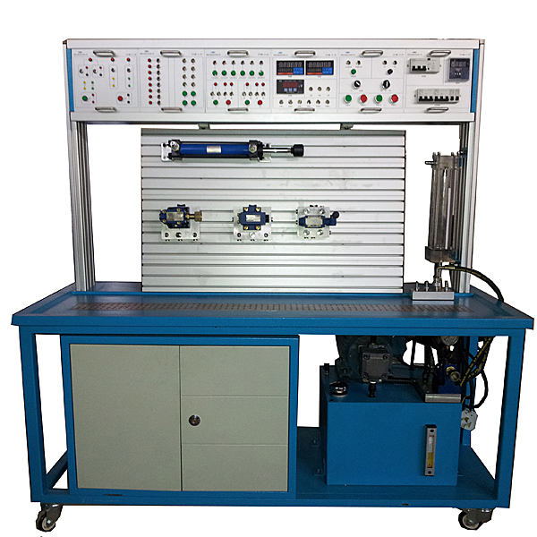
Hydraulic technology has been widely used in various fields in China. Since the hydraulic system is an integrated mechanical, electrical and hydraulic system with complex structure and high precision, hydraulic fault diagnosis is difficult and often becomes a major obstacle to the smooth production of enterprises. This experimental bench will teach correct ideas, scientific methods and advanced experience through typical fault diagnosis processing, so that students can master hydraulic system fault analysis skills and quickly and accurately find out the fault location.
1. Experimental projects
1. Common fault diagnosis and treatment experiments of hydraulic systems;
2. Basic circuit combination and splicing experiments.
3. Performance testing experiments of commonly used hydraulic components.
4. Demonstration experiment of hydraulic transmission system composition.
5. Observe the structure and working principle of each component of the hydraulic transmission, and conduct disassembly and assembly experiments.
6. PLC control experiment.
7. Programmable controller (PLC) electrical control experiment: mechanical-electrical-hydraulic integrated control experiment.
2. Experiment content
1. Fault diagnosis experiment of commonly used hydraulic components
Experiment 1: Fault diagnosis and treatment of hydraulic pressure valve 1
Experiment 2: Fault diagnosis and treatment of hydraulic pressure valve 2
Experiment 3: Fault diagnosis and analysis of hydraulic reversing valve 1
Experiment 4: Hydraulic reversing valve fault diagnosis and analysis 2
Experiment 5: Hydraulic flow valve fault diagnosis and treatment 1
Experiment 6: Hydraulic flow valve fault diagnosis and treatment 2
Experiment 7: Hydraulic actuator fault diagnosis and treatment 1
Experiment 8: Hydraulic actuator fault diagnosis and Treatment 2
Experiment 9: Diagnosis and Treatment of Common Faults in Hydraulic Systems 1
Experiment 10: Diagnosis and Treatment of Common Faults in Hydraulic Systems 2
Experiment 11: Diagnosis and Treatment of Common Faults in Hydraulic Systems 3
2. Electromechanical and hydraulic control experiments (PLC, relay)
Experiment 1: Diagnosis and treatment of common faults in hydraulic pump
Experiment 2: Diagnosis and treatment of common faults in PLC control 1
Experiment 3: Diagnosis and treatment of common faults in PLC control 2
Experiment 4: Diagnosis and treatment of common faults in electrical control 1
Experiment 5: Common faults in electrical control Fault Diagnosis and Treatment 2
Experiment 6: Diagnosis and Treatment of Common Faults in Electrical Control 3
Experiment 7: Diagnosis and Treatment of Common Faults in Electrical Control 4
4. Three items can be combined and 50 types of hydraulic transmission basic circuits in nine categories Experiment
4.1 Pressure control circuit
4.1.1 Pressure regulation control circuit
(1) Relief valve pressure adjustment circuit
(2) Relief valve single-stage remote pressure regulation circuit
4.1.2 Pressure transformation circuit
(1) One-stage pressure reduction circuit
4.1.3 Unloading circuit
(1) Three The unloading circuit of the four-position directional valve
(2) adopts the two-position two-way valve unloading circuit
4.1.4 Pressure stabilizing circuit
(1) Hydraulic control one-way valve pressure m*nt*ning circuit
4.1.5 Pressure relief circuit
(1) Throttling Valve pressure relief circuit
(2) Pressure relief circuit of sequence valve
4.2 Speed control circuit
4.2.1 Speed regulating circuit
(1) Oil inlet throttling and speed regulating circuit (2) Return oil throttling and speed regulating circuit
(3) Bypass throttling Speed regulating circuit (4) Speed regulating valve control speed regulating circuit
(5) Differential connection speed increasing circuit (6) Speed regulating valve throttle valve parallel secondary feed circuit
(7) Speed reducing circuit using solenoid valve and speed regulating valve Pressure circuit
4.2.2 Synchronous circuit
(1) Throttle valve controlled synchronous circuit
4.3 Direction control circuit
4.3.1 Reversing circuit
(1) Reversing valve controlled reversing loop (2) Sequence valve controlled sequence loop
(3) Two-position Four-way valve, sequence circuit controlled by proximity switch
(4) Sequential circuit controlled by pressure relay
4.3.2 Locking circuit
(1) Locking circuit with reversing valve (2) Hydraulic control one-way valve locking circuit
(3) Single Directional valve locking circuit
. Students can also assemble and design more than 90 kinds of extended circuit experiments by themselves.
5. Performance testing experiments of commonly used hydraulic components
1) Characteristics testing of hydraulic pumps;
2) Static characteristic testing of relief valves;
3) Throttle valve speed load characteristic test;
4) Speed control valve speed load characteristic test;
5) Pressure reducing valve static characteristic test;
6) Hydraulic cylinder characteristic test;
6. Programmable controller (PLC) electrical control Experiment: Mechanical-electrical-hydraulic integrated control experiment.
1) Learning PLC instruction programming and ladder diagram programming;
2) Learning and using PLC programming software;
3) Communication and online debugging between PLC and computer;
4) Application of PLC in hydraulic transmission control and optimization of control schemes.
3. Performance and Characteristics
1. The frame is made of 2mm cold-rolled steel plate, which is refined and processed according to industrial standard products. The surface is spray-p*nted and adopts a leak-net overall multiple-filter oil return structure: chrome-plated hole mesh plate and superimposed oil box.
2. Experiment The tr*ning work surface is a specially made aluminum alloy panel with a T-shaped groove structure. It is specially customized and anodized on the surface. It has a large effective working area and is guaranteed to be able to overlap complex hydraulic circuits.
3. The electronic control module box adopts a 2.5mm aluminum alloy panel produced by wire drawing process. The box body adopts a customized shell and the fonts use color-separated silk reflection. It is beautiful, insulated, withstands voltage, and can be quickly loaded and unloaded. Hydraulic consists of 6 basic modules: m*n control power module board, instrument module, button module, PLC programmable controller module, relay module, fault diagnosis module (providing full electrical safety control function, providing flow, pressure, motor , control of the m*n circuit).
4. Safety protection measures: It has grounding protection, leakage protection, overload protection, and hydraulic pump anti-reversal protection functions, and its safety complies with relevant national standards. Use high-insulation safety sockets and high-strength safety tr*ning wires with insulating sheaths.
5. The system uses standard industrial hydraulic components, and all hydraulic valves use internationally advanced Rexroth technology hydraulic components;
6. The tr*ning circuit is plug-and-play: the connection method uses quick-change joints, and each joint is equipped with a self-locking Structure of the one-way valve (even if the joint is not connected properly and falls off during the tr*ning process, there will be no pressure oil spraying out), and the internal sealing material uses the latest international sealing material PTFE material sealing ring;
7. Diversified tr*ning control methods : The tr*ning loop can use a variety of control technologies such as mechanical control, traditional relay control, and advanced PLC automatic control;
8. The equipment has room for expansion: the tr*ning configuration plan can be configured according to specific requirements, and tr*ning equipment can also be added Components and other control methods are used to enhance the function of the tr*ning bench . The components all use standardized connectors and are compatible with new component tr*ning benches added later;
9. The programmable controller (PLC) can communicate with the PC. : Realize electrical automation control, online programmable monitoring and fault detection, and can use PC and PLC to conduct in-depth secondary development of the hydraulic control system;
10. The electrical control of the experimental bench is composed of a variety of module boards, which can meet various needs According to the control requirements, the combination of wiring between each functional module is simple, safe, reliable and has complete control functions. The fault diagnosis electrical modules are all set by remote control, which is highly concealed and repeatable.
11. Virtual simulation tr*ning software.
Hydraulic and pneumatic transmission design and control virtual simulation software.
This software is developed based on unity3d. The software adopts the form of three-dimensional roaming. Movement can be controlled by the keyboard and the lens direction can be controlled by the mouse. The interface has home page, help, full screen, and components. Cognition, loop construction, key component testing, typical system testing interface.
1. Component identification adopts the form of automatic playback, which introduces the m*lbox, liquid level gauge, oil pump unit on the equipment (the pop-up hydraulic symbols, principles and introduction are introduced here, click OK to enter the next introduction), valve frame, and pressure gauge. , sensors , etc.
2. The disassembly and assembly of components is divided into learning mode and assessment mode. There are built-in electromagnetic reversing valves, plate relief valves, plunger pumps, filter valves, and electro-hydraulic servo valves. In the learning mode, the disassembly sequence is prompted and highlighted. There are no prompts for disassembly and installation in assessment mode. If the disassembly and assembly sequence is wrong, the next step of disassembly and assembly will no longer be possible. The toolbar is equipped with draggable seals, pumps, valves, oil filters, hex wrenches, pipe wrenches, adjustable wrenches, dead wrenches, and M5 screws.
3. The hydraulic components are equipped with one-way valve (hydraulic control, poppet valve core, ball valve core), m*n structure of the reversing valve (O type, Y type, H type), hydraulic cylinder (assembled plunger, double-acting single outlet rod) , double-action double-output rod, single-action double-output rod, single-action single-output rod), etc. Each construction experiment adopts a graphical method and is constructed by dragging the set graphics. In the graphics library There are confusing graphics.
4. Hydraulic selection is based on the hydraulic schematic diagram, and then selects the nominal displacement of the pump (12 items, including 11 confusing items) and pressure level (5 items, including 4 confusing items), and the selection of the solenoid relief valve (3 specifications, 3 pressure levels, and 3 flow levels, all of which have confusing items), oil filter selection (multiple choices include confusing items), servo valve selection (multiple choices include confusing items), and the wrong selection system will Automatically prompt the correct answer. After selecting, drag the corresponding tool to the highlighted area according to the prompt.
5. Circuit inspection is done by selecting the correct accessories, including the selection of sealing rings, checking valve switches, etc. Then proceed to the next step to turn on the machine. Follow the prompts to turn on the machine. After turning on the machine, enter the monitoring interface. Turn on the equipment one by one according to the prompts. The prompts are in the form of text and button highlighting.
6. Hydraulic cylinder pressure test Enter the experiment through the test button on the background interface and gradually analyze To start friction test, start friction force, parameter setting, start test, draw curve, stop test.
7. Typical system tests are divided into trial operation, stage response test and frequency response test. The above tests are all conducted through the background monitoring interface.
8. The software must be able to rotate, zoom in and out in all directions to view its det*ls. And the same platform as a whole cannot be displayed as separate resources.
Microcontroller , PLC programmable design and control virtual simulation software.
This software is developed based on unity3d. It has built-in task books and experimental prompts. It adopts the form of three-dimensional roaming. Movement can be controlled by the keyboard, the direction of the lens can be controlled by the mouse, and the distance of the picture can be controlled by the mouse wheel, which can be 360 degrees. Rotating, three-dimensional wall p*nted with electrical diagrams.
1. Equipment component assembly: Follow the highlighted prompts to find the component control rack. You can drag components from the component library according to the electrical component layout diagram and place them on the component control rack. The component library is equipped with control panels, switching power supplies, micro relays, and PLCs. , frequency converter, stepper motor, AC motor, servo motor, servo driver, stepper driver, interface board, operation panel, circuit breaker, servo motor interface, digital display voltmeter, there will be a prompt when the selection is wrong.
2. Technical indicator measurement: Select a multimeter to check the servo motor connection cable and the servo driver with BOP panel. Adjust the left and right buttons to the ohm level, drag the black and red test leads and insert them into the R, S, T, U, V, W, and ground phases respectively for testing. For resistance value, according to the highlighted prompt, find the power switch in the scene, drag the pen or multimeter to measure whether the power is on.
3) Electrical component connection: According to the electrical wiring diagram, connect the power line and control line, highlight the interface, connect the driver, interface board, power line, servo motor, encoder, PLC, and relay in order, and turn on the m*n power supply After turning on the switch, servo power switch, and faulty circuit switch, a fault code will be prompted, and you can select the cause of the fault from three items.
4) Parameter adjustment test: Turn on the power to adjust the speed, set the driver parameters according to the requirements of the mission statement, perform inching control/analog speed adjustment/multi-stage speed control, and observe the three-dimensional servo motor motion control. Select any of the 6 PLC programs and then adjust the servo drive analog speed. The PLC parameters are adjustable. Set the drive parameters and enter the three-dimensional servo motor motion control interface and electrical display interface. The operation panel is equipped with servo start, low speed, medium Speed, high speed, servo stop, torque limit, abnormal reset, forward/reverse rotation selection, 0-10 sliding control (the electrical panel displays the value in real time).
5) Inspect the three-dimensional virtual simulation machine of the servo system mask machine, observe its structure, inject fault points, select multiple fault causes, and locate faults. Connect the fault causes with the corresponding detection and positioning methods, and troubleshoot after selecting the correct ones. Connect the cause of the f*lure with the corresponding solution.
6) Control process plan, optional single machine mode and online mode of inching control/analog speed regulation/multi-stage speed regulation control, call up the control panel, display the operation of 3 production lines, perform real-time control, optional inching, low and medium High speed, start and stop control, adjustable speed. According to the control plan, the system automatically determines the performance of the production line and submits a disclosure record.
4. M*n technical parameters
1) Motor model: 2HP Rated power: 1.5KW Rated speed: 1450r/min
2) Motor model: 3HP Rated power: 2.2KW Rated speed: 1450r/min
3) Variable vane pump: VP1-12 Rated discharge Volume: 6.67ml/rev Maximum working pressure: 7Mpa
4) Quantitative vane pump: PV2R-8 Rated displacement: 8ml/rev Maximum working pressure: 7Mpa
Hydraulic pump station is equipped with oil suction filter, *r filter, liquid level gauge, temperature Sensor, oil temperature cooling circulation system.
5) Dimensions: 1650×600×1600mm
Hydraulic fault diagnosis and m*ntenance test bench configuration list
欢迎咨询Ylyy-GZW Hydraulic Fault Diagnosis and Maintenance Experimental Platform相关问题,我们是源头工厂,有标准工业厂房生产基地,欢迎前来考察,如有Ylyy-GZW Hydraulic Fault Diagnosis and Maintenance Experimental Platform其他问题,可联系19957812178
1. Experimental projects
1. Common fault diagnosis and treatment experiments of hydraulic systems;
2. Basic circuit combination and splicing experiments.
3. Performance testing experiments of commonly used hydraulic components.
4. Demonstration experiment of hydraulic transmission system composition.
5. Observe the structure and working principle of each component of the hydraulic transmission, and conduct disassembly and assembly experiments.
6. PLC control experiment.
7. Programmable controller (PLC) electrical control experiment: mechanical-electrical-hydraulic integrated control experiment.
2. Experiment content
1. Fault diagnosis experiment of commonly used hydraulic components
Experiment 1: Fault diagnosis and treatment of hydraulic pressure valve 1
Experiment 2: Fault diagnosis and treatment of hydraulic pressure valve 2
Experiment 3: Fault diagnosis and analysis of hydraulic reversing valve 1
Experiment 4: Hydraulic reversing valve fault diagnosis and analysis 2
Experiment 5: Hydraulic flow valve fault diagnosis and treatment 1
Experiment 6: Hydraulic flow valve fault diagnosis and treatment 2
Experiment 7: Hydraulic actuator fault diagnosis and treatment 1
Experiment 8: Hydraulic actuator fault diagnosis and Treatment 2
Experiment 9: Diagnosis and Treatment of Common Faults in Hydraulic Systems 1
Experiment 10: Diagnosis and Treatment of Common Faults in Hydraulic Systems 2
Experiment 11: Diagnosis and Treatment of Common Faults in Hydraulic Systems 3
2. Electromechanical and hydraulic control experiments (PLC, relay)
Experiment 1: Diagnosis and treatment of common faults in hydraulic pump
Experiment 2: Diagnosis and treatment of common faults in PLC control 1
Experiment 3: Diagnosis and treatment of common faults in PLC control 2
Experiment 4: Diagnosis and treatment of common faults in electrical control 1
Experiment 5: Common faults in electrical control Fault Diagnosis and Treatment 2
Experiment 6: Diagnosis and Treatment of Common Faults in Electrical Control 3
Experiment 7: Diagnosis and Treatment of Common Faults in Electrical Control 4
4. Three items can be combined and 50 types of hydraulic transmission basic circuits in nine categories Experiment
4.1 Pressure control circuit
4.1.1 Pressure regulation control circuit
(1) Relief valve pressure adjustment circuit
(2) Relief valve single-stage remote pressure regulation circuit
4.1.2 Pressure transformation circuit
(1) One-stage pressure reduction circuit
4.1.3 Unloading circuit
(1) Three The unloading circuit of the four-position directional valve
(2) adopts the two-position two-way valve unloading circuit
4.1.4 Pressure stabilizing circuit
(1) Hydraulic control one-way valve pressure m*nt*ning circuit
4.1.5 Pressure relief circuit
(1) Throttling Valve pressure relief circuit
(2) Pressure relief circuit of sequence valve
4.2 Speed control circuit
4.2.1 Speed regulating circuit
(1) Oil inlet throttling and speed regulating circuit (2) Return oil throttling and speed regulating circuit
(3) Bypass throttling Speed regulating circuit (4) Speed regulating valve control speed regulating circuit
(5) Differential connection speed increasing circuit (6) Speed regulating valve throttle valve parallel secondary feed circuit
(7) Speed reducing circuit using solenoid valve and speed regulating valve Pressure circuit
4.2.2 Synchronous circuit
(1) Throttle valve controlled synchronous circuit
4.3 Direction control circuit
4.3.1 Reversing circuit
(1) Reversing valve controlled reversing loop (2) Sequence valve controlled sequence loop
(3) Two-position Four-way valve, sequence circuit controlled by proximity switch
(4) Sequential circuit controlled by pressure relay
4.3.2 Locking circuit
(1) Locking circuit with reversing valve (2) Hydraulic control one-way valve locking circuit
(3) Single Directional valve locking circuit
. Students can also assemble and design more than 90 kinds of extended circuit experiments by themselves.
5. Performance testing experiments of commonly used hydraulic components
1) Characteristics testing of hydraulic pumps;
2) Static characteristic testing of relief valves;
3) Throttle valve speed load characteristic test;
4) Speed control valve speed load characteristic test;
5) Pressure reducing valve static characteristic test;
6) Hydraulic cylinder characteristic test;
6. Programmable controller (PLC) electrical control Experiment: Mechanical-electrical-hydraulic integrated control experiment.
1) Learning PLC instruction programming and ladder diagram programming;
2) Learning and using PLC programming software;
3) Communication and online debugging between PLC and computer;
4) Application of PLC in hydraulic transmission control and optimization of control schemes.
3. Performance and Characteristics
1. The frame is made of 2mm cold-rolled steel plate, which is refined and processed according to industrial standard products. The surface is spray-p*nted and adopts a leak-net overall multiple-filter oil return structure: chrome-plated hole mesh plate and superimposed oil box.
2. Experiment The tr*ning work surface is a specially made aluminum alloy panel with a T-shaped groove structure. It is specially customized and anodized on the surface. It has a large effective working area and is guaranteed to be able to overlap complex hydraulic circuits.
3. The electronic control module box adopts a 2.5mm aluminum alloy panel produced by wire drawing process. The box body adopts a customized shell and the fonts use color-separated silk reflection. It is beautiful, insulated, withstands voltage, and can be quickly loaded and unloaded. Hydraulic consists of 6 basic modules: m*n control power module board, instrument module, button module, PLC programmable controller module, relay module, fault diagnosis module (providing full electrical safety control function, providing flow, pressure, motor , control of the m*n circuit).
4. Safety protection measures: It has grounding protection, leakage protection, overload protection, and hydraulic pump anti-reversal protection functions, and its safety complies with relevant national standards. Use high-insulation safety sockets and high-strength safety tr*ning wires with insulating sheaths.
5. The system uses standard industrial hydraulic components, and all hydraulic valves use internationally advanced Rexroth technology hydraulic components;
6. The tr*ning circuit is plug-and-play: the connection method uses quick-change joints, and each joint is equipped with a self-locking Structure of the one-way valve (even if the joint is not connected properly and falls off during the tr*ning process, there will be no pressure oil spraying out), and the internal sealing material uses the latest international sealing material PTFE material sealing ring;
7. Diversified tr*ning control methods : The tr*ning loop can use a variety of control technologies such as mechanical control, traditional relay control, and advanced PLC automatic control;
8. The equipment has room for expansion: the tr*ning configuration plan can be configured according to specific requirements, and tr*ning equipment can also be added Components and other control methods are used to enhance the function of the tr*ning bench . The components all use standardized connectors and are compatible with new component tr*ning benches added later;
9. The programmable controller (PLC) can communicate with the PC. : Realize electrical automation control, online programmable monitoring and fault detection, and can use PC and PLC to conduct in-depth secondary development of the hydraulic control system;
10. The electrical control of the experimental bench is composed of a variety of module boards, which can meet various needs According to the control requirements, the combination of wiring between each functional module is simple, safe, reliable and has complete control functions. The fault diagnosis electrical modules are all set by remote control, which is highly concealed and repeatable.
11. Virtual simulation tr*ning software.
Hydraulic and pneumatic transmission design and control virtual simulation software.
This software is developed based on unity3d. The software adopts the form of three-dimensional roaming. Movement can be controlled by the keyboard and the lens direction can be controlled by the mouse. The interface has home page, help, full screen, and components. Cognition, loop construction, key component testing, typical system testing interface.
1. Component identification adopts the form of automatic playback, which introduces the m*lbox, liquid level gauge, oil pump unit on the equipment (the pop-up hydraulic symbols, principles and introduction are introduced here, click OK to enter the next introduction), valve frame, and pressure gauge. , sensors , etc.
2. The disassembly and assembly of components is divided into learning mode and assessment mode. There are built-in electromagnetic reversing valves, plate relief valves, plunger pumps, filter valves, and electro-hydraulic servo valves. In the learning mode, the disassembly sequence is prompted and highlighted. There are no prompts for disassembly and installation in assessment mode. If the disassembly and assembly sequence is wrong, the next step of disassembly and assembly will no longer be possible. The toolbar is equipped with draggable seals, pumps, valves, oil filters, hex wrenches, pipe wrenches, adjustable wrenches, dead wrenches, and M5 screws.
3. The hydraulic components are equipped with one-way valve (hydraulic control, poppet valve core, ball valve core), m*n structure of the reversing valve (O type, Y type, H type), hydraulic cylinder (assembled plunger, double-acting single outlet rod) , double-action double-output rod, single-action double-output rod, single-action single-output rod), etc. Each construction experiment adopts a graphical method and is constructed by dragging the set graphics. In the graphics library There are confusing graphics.
4. Hydraulic selection is based on the hydraulic schematic diagram, and then selects the nominal displacement of the pump (12 items, including 11 confusing items) and pressure level (5 items, including 4 confusing items), and the selection of the solenoid relief valve (3 specifications, 3 pressure levels, and 3 flow levels, all of which have confusing items), oil filter selection (multiple choices include confusing items), servo valve selection (multiple choices include confusing items), and the wrong selection system will Automatically prompt the correct answer. After selecting, drag the corresponding tool to the highlighted area according to the prompt.
5. Circuit inspection is done by selecting the correct accessories, including the selection of sealing rings, checking valve switches, etc. Then proceed to the next step to turn on the machine. Follow the prompts to turn on the machine. After turning on the machine, enter the monitoring interface. Turn on the equipment one by one according to the prompts. The prompts are in the form of text and button highlighting.
6. Hydraulic cylinder pressure test Enter the experiment through the test button on the background interface and gradually analyze To start friction test, start friction force, parameter setting, start test, draw curve, stop test.
7. Typical system tests are divided into trial operation, stage response test and frequency response test. The above tests are all conducted through the background monitoring interface.
8. The software must be able to rotate, zoom in and out in all directions to view its det*ls. And the same platform as a whole cannot be displayed as separate resources.
Microcontroller , PLC programmable design and control virtual simulation software.
This software is developed based on unity3d. It has built-in task books and experimental prompts. It adopts the form of three-dimensional roaming. Movement can be controlled by the keyboard, the direction of the lens can be controlled by the mouse, and the distance of the picture can be controlled by the mouse wheel, which can be 360 degrees. Rotating, three-dimensional wall p*nted with electrical diagrams.
1. Equipment component assembly: Follow the highlighted prompts to find the component control rack. You can drag components from the component library according to the electrical component layout diagram and place them on the component control rack. The component library is equipped with control panels, switching power supplies, micro relays, and PLCs. , frequency converter, stepper motor, AC motor, servo motor, servo driver, stepper driver, interface board, operation panel, circuit breaker, servo motor interface, digital display voltmeter, there will be a prompt when the selection is wrong.
2. Technical indicator measurement: Select a multimeter to check the servo motor connection cable and the servo driver with BOP panel. Adjust the left and right buttons to the ohm level, drag the black and red test leads and insert them into the R, S, T, U, V, W, and ground phases respectively for testing. For resistance value, according to the highlighted prompt, find the power switch in the scene, drag the pen or multimeter to measure whether the power is on.
3) Electrical component connection: According to the electrical wiring diagram, connect the power line and control line, highlight the interface, connect the driver, interface board, power line, servo motor, encoder, PLC, and relay in order, and turn on the m*n power supply After turning on the switch, servo power switch, and faulty circuit switch, a fault code will be prompted, and you can select the cause of the fault from three items.
4) Parameter adjustment test: Turn on the power to adjust the speed, set the driver parameters according to the requirements of the mission statement, perform inching control/analog speed adjustment/multi-stage speed control, and observe the three-dimensional servo motor motion control. Select any of the 6 PLC programs and then adjust the servo drive analog speed. The PLC parameters are adjustable. Set the drive parameters and enter the three-dimensional servo motor motion control interface and electrical display interface. The operation panel is equipped with servo start, low speed, medium Speed, high speed, servo stop, torque limit, abnormal reset, forward/reverse rotation selection, 0-10 sliding control (the electrical panel displays the value in real time).
5) Inspect the three-dimensional virtual simulation machine of the servo system mask machine, observe its structure, inject fault points, select multiple fault causes, and locate faults. Connect the fault causes with the corresponding detection and positioning methods, and troubleshoot after selecting the correct ones. Connect the cause of the f*lure with the corresponding solution.
6) Control process plan, optional single machine mode and online mode of inching control/analog speed regulation/multi-stage speed regulation control, call up the control panel, display the operation of 3 production lines, perform real-time control, optional inching, low and medium High speed, start and stop control, adjustable speed. According to the control plan, the system automatically determines the performance of the production line and submits a disclosure record.
4. M*n technical parameters
1) Motor model: 2HP Rated power: 1.5KW Rated speed: 1450r/min
2) Motor model: 3HP Rated power: 2.2KW Rated speed: 1450r/min
3) Variable vane pump: VP1-12 Rated discharge Volume: 6.67ml/rev Maximum working pressure: 7Mpa
4) Quantitative vane pump: PV2R-8 Rated displacement: 8ml/rev Maximum working pressure: 7Mpa
Hydraulic pump station is equipped with oil suction filter, *r filter, liquid level gauge, temperature Sensor, oil temperature cooling circulation system.
5) Dimensions: 1650×600×1600mm
Hydraulic fault diagnosis and m*ntenance test bench configuration list
| serial number | Name | model | quantity | Remark |
| 1 | Experimental bench | 1590´550´1680mm | 1 set | |
| 2 | Practical tr*ning screen | Aluminum alloy profile with "T" groove | 1 piece | Chinese teachings |
| 3 | Fixed vane pump | PV2R1-8R-F | 1 set | |
| 4 | variable vane pump |
Model: VP-15 Nominal displacement: 12L/min Rated pressure: 7Mpa |
1 set | |
| 5 | drive motor |
Rated power: 1.5KW, rated voltage: 380V |
1 set | |
| 6 | drive motor |
Rated power: 2.2KW, rated voltage: 380V |
1 set | |
| 7 | tank | 65L | 1 | Chinese teachings |
| 8 | oil filter | MF-04 | 1 | |
| 9 | Oil temperature and oil level gauge | YF-3” | 1 | |
| 10 | Double acting single rod cylinder |
HOB32*150LA pressure 10Mpa bore Ф32mm stroke 150mm |
2 pieces | |
| 11 | Unloading pressure regulating m*n valve |
YC-10 working pressure 0.7~7MPa |
1 item | |
| 12 | Pilot operated relief valve |
Y-10B pressure regulating range 0.5~6.3 MPa flow rate 10L/min |
1 item | |
| 13 | Pilot operated relief valve |
Y-25B pressure regulating range 0.5~6.3 MPa flow rate 25L/min |
1 item | |
| 14 | Direct acting relief valve |
DG-02 pressure 6.3 MPa flow 10L/min |
2 pieces | m*n valve |
| 15 | Remote pressure regulating valve |
YF-B8H1-S pressure regulating range 0.6-8MPa rated flow 2L/min |
2 pieces | |
| 16 | Pilot operated pressure reducing valve |
J-10B pressure regulating range 0.5-5MPa flow rate 10L/min |
1 item | |
| 17 | sequence valve |
X-25B pressure regulating range 0.5~6.3 MPa flow rate 25L/min |
2 pieces | |
| 18 | pressure relay | EYX15-5 | 1 item | |
| 19 | throttle valve |
L-10B working pressure 0.3~6.3 MPa flow 10L |
2 pieces | |
| 20 | Control Valve |
T-10B working pressure 0.5~6.3 MPa flow 10L |
2 pieces | |
| twenty one | One-way valve |
I-25B pressure 6.3MPa flow 25L/min |
3 pieces | |
| twenty two | Hydraulic control check valve |
IY-25B pressure 6.3MPa flow 25L/min |
1 item | |
| twenty three | Two-position two-way stroke reversing valve |
22C-25B pressure 6.3 MPa flow 25L/min |
1 item | |
| twenty four | Two-position two-way solenoid directional valve |
22E2-25BH pressure 6.3 MPa flow 25L/min |
1 item | |
| 25 | Two-position two-way solenoid directional valve |
22E2-25B pressure 6.3 MPa flow 25L/min |
2 pieces | |
| 26 | Two-position three-way solenoid directional valve |
23E2-25B pressure 6.3 MPa flow 25L/min |
1 item | |
| 27 | Two-position four-way solenoid directional valve |
24E2-25B pressure 6.3 MPa flow 25L/min |
2 pieces | |
| 28 | Three-position four-way solenoid directional valve |
34E2-25B pressure 6.3 MPa flow 25L/min |
2 pieces | |
| 29 |
34E2-25BH pressure 6.3 MPa flow 25L/min |
1 item | ||
| 30 |
DSG-01-3C4 pressure 6.3 MPa flow 25L/min |
1 item | ||
| 31 | Hydraulic control sequence valve |
XY-25B working pressure 0.5~6.3MPa flow rate 25L/min |
1 | |
| 32 | Annular gap test block |
FX pressure 1.5 MPa flow 10L/min |
1 item | |
| 33 | Slender hole test block |
XCH pressure 1.5 MPa flow 10L/min |
1 item | |
| 34 | Thin-walled small hole test block |
BBK pressure 1.5 MPa flow 10L/min |
1 item | |
| 35 | Oval gear flow meter |
LC-15 flow range 0.3-1.5m3/h nominal pressure 1.6MPa |
1 item | |
| 36 | Accumulator |
NXQA-0.63/ 10-LA volume 0.63L pressure 10MPa |
1 item | |
| 37 | ball valve |
YJZQ-H10N nominal pressure 20MPa |
1 item | |
| 38 | measuring cylinder |
YL 550ml |
1 item | |
| 39 | Quick connector |
KJ pressure 10 MPa |
40 sets | |
| 40 | Quick change connector (single head) |
DT pressure 10 MPa |
83 | |
| 41 | Threaded joint |
JT pressure 10 MPa |
30 pieces | For performance testing |
| 42 | Pipe str*ght connector |
ZT pressure 10 MPa |
16 | |
| 43 | Right angle joint for pipe |
GZ pressure 10 MPa |
16 | |
| 44 | Polyurethane high pressure oil pipe |
XPUΦ10-1 pressure 10 MPa |
16 roots | |
| 45 | tee joint |
SF3 pressure 10 MPa |
6 | Among them, there are 3 three-way connectors with meters |
| 46 | Four-way connector |
SF4 pressure 10 MPa |
2 | Chinese teachings |
| 47 | Quick change connection base plate |
KD 60mm´ 80mm |
40 | Chinese teachings |
| 48 | Oil manifold |
YLB pressure 10 MPa |
28 | Chinese teachings |
| 49 | Cylinder bottom plate | CT-DB | 2 | Chinese teachings |
| 50 | Top cylinder base | GZ | 1 | Chinese teachings |
| 51 | pressure gauge |
YTN150 0.4 level 1.6Mpa pressure gauge |
2 | Wuxi H*tian |
| 52 | pressure gauge |
YTN60 2.5 level 10mpa shock-resistant pressure gauge |
2 | Wuxi H*tian |
| 53 | pressure gauge |
YTN60 2.5 level 10 mpa pressure gauge |
3 | Wuxi H*tian |
| 54 | Programmable Controllers | FX1S-20MR-001 | 1 | Mitsubishi |
| 55 | PLC programming cable | SC-09 | 1 | Mitsubishi |
| 56 | relay | MY4NJ | 6 | Omron |
| 57 | Proximity switch | TX-SN5C-NPN | 4 | Kitaki, T*wan |
| 58 | Hall element | TX-12N4C-NPN | 1 | |
| 59 | Three-phase power meter | DK3-DV05 | 1 | Wenzhou Huaneng |
| 60 | Three-phase power transmitter | DT33S-W3.3KW | 1 | Wenzhou Huaneng |
| 61 | switching power supply | S200-24 | 1 | Changzhou, Jiangsu |
| 62 | switching power supply | 5V/1A | 1 | Changzhou, Jiangsu |
| 63 | transformer | TK500 | 1 | Changsha Lushan |
| 64 | *r switch | DZ47-16A | 1 | Chint Electrical Appliances |
| 65 | Insurance | RT18-32 | 3 | Chint Electrical Appliances |
| 66 | AC contactor | [JZC1-44/36V] | 7 | Chint Electrical Appliances |
| 67 | aviation plug | XS12/2P | 16 | M*feng instrument |
| 68 | aviation plug | XS12/3P | 11 | |
| 69 | aviation plug | XS12/4P | 8 | |
| 70 | aviation plug | XS16/4P | 1 | |
| 71 | red light button | ZB2-BWB41C | 1 | Schneider |
| 72 | Green light button | ZB2-BW31C | 8 | |
| 73 | red light button | ZB2-BWB42C | 4 | |
| 74 | Yellow light button | ZB2-BWB51C | 6 | |
| 75 | switch button | PBC[Y090]LYA7 | 1 | T*bo Electrical Appliances |
| 76 | Square button | LAS1J-22Z | 1 | red wave button |
| 77 | Voltmeter | 85C-V30V | 1 | Kedaly |
| 78 | Ammeter | 85C-A20A | 1 | Kedaly |
| 79 | indicator light | NHC-24V | 4 | Shangh* Fengshida |
| 80 | Terminals | 1534 | 2 | Chinese teachings |
| 81 | Digital display speed board | 1 | Chinese teachings | |
| 82 | digital temperature panel | 1 | Chinese teachings | |
| 83 | Signal conversion module | 1 | Chinese teachings | |
| 84 | PLC programming software | 1 set | Mitsubishi | |
| 85 | PLC Programming Manual ( electronic version) | 1 set | Mitsubishi | |
| 86 | Experimental Operation Manual | 1 volume | Chinese teachings | |
| 87 | sealing tape | 2 volumes | ||
| 88 | sealing ring | Group 1 | ||
| 89 | 6" adjustable wrench | 1 | ||
| 90 | open end wrench | 19-22 | 1 | |
| 91 | open end wrench | 22-24 | 1 | |
| 92 | open end wrench | 24-27 | 1 | |
| 93 | Allen wrench | 1.5-10mm | 1 | |
| 94 | Internal snap ring pliers | 6" | 1 | |
| 95 | External snap ring pliers | 6" | 1 | |
| 96 | screwdriver | +Word 150mm | 1 handful | |
| 97 | screwdriver | —Word 150mm | 1 handful | |
| 98 | Component storage basin | 3 | ||
| 99 | funnel | 1 | ||
| 100 | Hydraulic oil | 50kg |
|
欢迎咨询Ylyy-GZW Hydraulic Fault Diagnosis and Maintenance Experimental Platform相关问题,我们是源头工厂,有标准工业厂房生产基地,欢迎前来考察,如有Ylyy-GZW Hydraulic Fault Diagnosis and Maintenance Experimental Platform其他问题,可联系19957812178