简体中文
简体中文 English
 Spanish


Product 

Features of the device
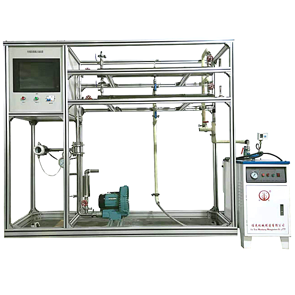
1. The entire device is beautiful and elegant, with reasonable structural design and strong engineering flavor, which can fully embody the concept of a modern laboratory .
2. The equipment layout is reasonable and beautiful, with clear structure and strong sense of integrity, and can reflect the concept of m*n experimental equipment in the laboratory.
3. The entire equipment is a self-propelled frame structure and is equipped with restr*ning feet to facilitate disassembly, m*ntenance and transportation of the system.
4. Except for special materials, the entire set of equipment is made of industrial 304 st*nless steel. All equipment is finely polished, which reflects the process perfection of the entire device.
5. The experimental system device integrates the calibration of two flow meters, Venturi and orifice flow meters, so that students can learn correct flow measurement and understand the correct pressure induction method.
6. Experimental projects can be selected through valve adjustment switching, and the fluid outlet is designed with a full pipe section; the fluid flow is adjusted by a gate valve, and the flow measurement uses a turbine flowmeter and a digital instrument system; the throttling pressure difference uses a pressure sensor and a digital instrument system.
7. The entire system adopts standard industrial instrument control system, which can carry out experiments on chemical engineering principles . It is also a good platform for process automation and chemical testing instrument experiments.
8. The device design allows for 360-degree observation, enabling all-round teaching and experimentation.
Device functions
1. Understand the structure, working principle and m*n characteristics of turbine flowmeter, orifice flowmeter, venturi flowmeter and rotameter.
2. Master the calibration method of flow meter.
3. Understand the changing pattern of the flow coefficient C of the throttling flowmeter with the Reynolds number Re, and the method for determining the flow coefficient C.
4. Learn how to choose a coordinate system reasonably. Learn to calibrate the flow rate using a standard flow meter.
5. Determine the flow calibration curve of the throttling flow meter (orifice plate, venturi).
6. Determine the relationship between the Reynolds number Re and the flow coefficient C of the throttling flowmeter, and compare them.
7. Determine the flow calibration curve of the rotameter.
8. Full touch integrated control, highly stable data transmission, and hardware encryption.
Design parameters
Orifice flowmeter flow rate: 0.4~8m3/h, pressure difference range: 10~100KPa.
Venturi flow meter flow rate: 0.4~8m3/h, pressure difference range: 10~150KPa.
Rotameter flow rate: 0.4~4m3/h.
Turbine flowmeter flow rate: 0.4~8m3/h.
Temperature: normal temperature.
Utilities
Water: The unit comes with a st*nless steel water tank and is connected to tap water. During the experiment, it enters the test pipeline through the centrifugal pump and is recycled.
Electricity: voltage AC220V, power 1.0KW, standard single-phase three-wire system. Each laboratory needs to be equipped with 1~2 grounding points (safety ground and signal ground).
Experimental materials: clean tap water. External equipment: None.
M*n equipment
1. Water rotor flowmeter: Flow range 0.4~4m3/h.
2. Orifice plate flowmeter: flow range 0.4~8m3/h, orifice plate flowmeter: orifice plate throat diameter: Φ17mm.
3. Venturi flow meter: flow range 0.4~8m3/h, Venturi flow meter: Venturi throat diameter: Φ13mm.
4. Turbine flowmeter: flow range 0.4~8.0m3/h, 4-20mA remote transmission output, flow detection mechanism .
5. Differential pressure sensor: measuring range 0~150KPa, 4-20mA remote transmission, differential pressure detection mechanism.
6. 304 st*nless steel centrifugal pump: power 550W, maximum flow 6m3/h.
7. Water tank: made of 304 st*nless steel, with a volume of ≥100L, with a water storage and emptying bottom valve, and a partition plate design between the pipeline return water and the pump suction inlet.
8. Temperature sensor: Pt100, resolution 0.1℃, accuracy 0.5%.
9. Electrical appliances: contactors, switches, leakage protection *r switches.
10. Central processing unit: execution speed 0.64μs, memory capacity ≥16K; built-in RS485 communication mode; function: acquisition and conversion of analog signals such as temperature and pressure.
11. Analog module: up to 16-bit resolution, sum accuracy ±0.5%.
12. Temperature module: resolution 0.1℃, accuracy 0.5%, built-in RS485 communication mode.
13. Display terminal: It adopts an all-in-one tablet touch computer and the entire digital touch screen control operation. HMI: Projected touch technology, 50 million touch points, 4G memory, function: central processor data display control;
14. Rated voltage: 220V, total power: 1kW;
15. Overall dimensions: 2000×550×1800mm (length × width
16. Engineering identification: including equipment serial numbers, pipeline flow direction arrows and logos, valve serial numbers and other engineering equipment concepts to keep students in a safe experimental operating environment.
17. The supporting measurement and control software can realize real-time online collection and display of experimental data, curves and equipment operating status. Terminal coverage is achieved through WIFI technology.
18. Building and intelligent building electricalInstall virtual simulation software
Based on unity3d design, users can choose different sizes of interactive interfaces according to computer configuration, and can choose six levels of image quality. The model in the software can be rotated 360°, enlarged, reduced, and translated. There are assistant prompts during the use of the software, as follows:
A. Wet alarm system
1. System overview: Overview of wet alarm system
2. Equipment recognition: It has the best viewing angle, equipment det*ls (displaying the introduction or parameters of the equipment), exercises (built-in 6 multiple-choice questions, with prompts for correct and wrong choices), and schematic diagrams (you can enter the equipment from the schematic diagram). The equipment includes: sprinklers, water flow indicators, signal butterfly valves, exhaust valves, fire alarm controls, high-pressure gauges, high-level water tanks, Wia control cabinets, pressure regulators, flow switches, end water test devices, dr*nage facilities, water pump connectors, hydraulic alarms, delay devices, wet alarms, butterfly valves, check valves, fire pumps, safety pressure regulators, and fire water tanks.
3. Principle display: Display the working principle of the wet alarm system, 3D animation demonstration, and semi-transparent 3D models, so that the internal water flow can be seen. Equipped with practice module (built-in 4 multiple-choice questions, with prompts for correct and wrong choices)
4. Design layout: There are multiple-choice questions and calculation questions, each of which is scored, and the correct answer and score will be displayed after submission
B. Gas fire extinguishing system
1. System overview: Overview of gas fire extinguishing system
2. Equipment recognition: It is equipped with the best viewing angle, equipment det*ls (displaying the introduction or parameters of the equipment), practice (built-in 8 multiple-choice questions, with prompts for correct and wrong choices), schematic diagram (you can enter the equipment from the schematic diagram). The equipment includes: nozzle, HFC-227 storage bottle, bottle head valve, heptafluoropropane check valve, high-pressure hose, gas check valve, safety valve, weighing alarm, electromagnetic starter, selection valve, smoke alarm, fire alarm controller.
3. Principle display: Display the working principle of the gas fire extinguishing system, 3D animation demonstration, 3D model is semi-transparent, and the internal gas can be seen. Equipped with practice module (built-in 3 multiple-choice questions, with prompts for correct and wrong choices)
4. Design and layout: There are 6 multiple-choice questions, each with scores, and the correct answer and score will be displayed after submission
. C. Escape drill: Teaching in the form of fun games, escape from the burning room within a limited time, and wrong choices will directly enter the score interface.
欢迎咨询YLHGYL-20 flow meter school training device相关问题,我们是源头工厂,有标准工业厂房生产基地,欢迎前来考察,如有YLHGYL-20 flow meter school training device其他问题,可联系19957812178