简体中文
简体中文 English
 Spanish


Product 

The logic control of the elevator system is completed by PLC (can be connected online). The PLC is from Mitsubishi of Japan, and its output mode is relay output. The communication between PLC and PC can be realized through the RS422 or RS232 interface equipped on the host. Using GX-Developer software, you can directly program and debug with ladder diagrams on the PC, which is intuitive and easy to learn, and easy for beginners to master; in addition, you can also use FP programmer II for instruction programming and direct debugging on site.
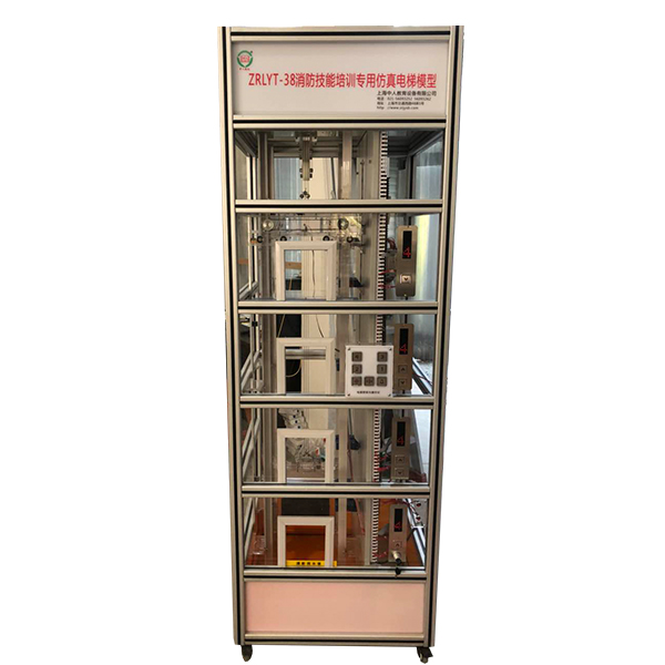
Transparent simulation teaching elevator complete set of equipment:
1. Fire elevator model host - including Mitsubishi FX3U-64MR programmable controller (PLC);
2. PLC peripheral special communication cable;
3. Mitsubishi programmer operation manual;
4. Mitsubishi PLC special programming tool software;
5. Teaching elevator instruction manual.
Basic structure of elevator:
1. Machine room part: The reduction motor realizes the up and down movement of the elevator.
2. Hoistway part: including guide r*ls, counterweight mechanism , car, floor call indicator controller, traction rope, guide wheel, one-layer leveling sensor, upper (lower) limit switch, upper (lower) limit switch, accompanying cable, car controller, buffer, etc.
3. Electrical control part: power *r switch (leakage release), DC24V drive power supply, PLC programmable controller, wiring port circuit board.
The elevator car position detection and electrical floor selection signal are obt*ned by the bistable magnetic switch installed on the top of the car and each floor station, thus getting rid of the complex line system controlled by contact devices such as relays and contact switches in the past, optimizing the line, greatly improving the reliability of system operation, and also facilitating m*ntenance.
A. Spring buffer device for car and counterweight Buffer
is a safety device for the elevator limit position. When the elevator f*ls and causes the car or counterweight to hit the bottom or top, the car or counterweight hits the spring buffer, and the buffer absorbs the energy of the elevator, so that the car or counterweight can be safely decelerated until it stops.
B. Terminal limit switch safety protection system
Terminal limit switches are installed on the top and bottom of the elevator shaft. When the elevator loses control due to a fault and the car hits the top or squats at the bottom, the terminal limit switch cuts off the control circuit and stops the car.
C. Fire call system and fire linkage action channel
D. Shaft lighting system
E. Bottom virtual water pump system
F. Fire dr*nage device
G. Car bottom device
H. Fire water ret*ning device
I. Virtual simulation system for comprehensive integrated tr*ning of professional skills The model
in the software can be rotated 360°, enlarged, reduced, and translated, and there are general interactive buttons: return, home page, help. There are prompts for all virtual simulation task processes, and the software automatically ticks after completing a task. There are experimental tasks 1 and basic solids above the tool library (the XYZ space coordinate icon automatically rotates with the rotation when the model is rotated.) A. Plane solids: The experimental steps are divided into experimental tasks (text prompt tasks) - build models (drag the model in the tool library to the three-projection surface system, and the projection will be automatically displayed. There will be prompts when the selection is wrong) - change posture (change by clicking the up, down, left, and right arrows) - select projection (enter the answering interface, and select the three-dimensional projection diagram completed at this time from the 6 items) B. Cutting solids: The experimental steps are divided into experimental tasks (text prompt tasks) - build models (drag the model in the tool library to the three-projection surface system, and the projection will be automatically displayed) - mark the projection situation (mark the three-dimensional projection diagram, and select the corresponding marking symbol in the 14 blank columns) C. Intersecting solids: The experimental steps are divided into experimental tasks (text prompt tasks) - digging holes (select any digging hole model, then you can select any surface in the XYZ space coordinates, the models will switch at the same time, and a coordinate slider will appear. According to the displacement of the slider, the model will have a corresponding degree of cross-section) - aperture change (select 1-4 apertures) - rear through hole - select projection (enter the answering interface, and select the completed three-dimensional projection diagram at this time in 8 items) 2. Assembly A. Assembly assembly: The experimental steps are divided into experimental tasks (text prompt tasks) - select the assembly model (8 models can be selected) - assemble the assembly (select the tool library model according to the selected model and drag and drop the assembly) - section the assembly (you can select any surface in the XYZ space coordinates, the models will switch at the same time, and a coordinate slider will appear. According to the displacement of the slider, the model will have a corresponding degree of cross-section) - select side projection (enter the answering interface, based on the known front and horizontal projection diagrams, select the correct side projection diagram in 3 items) B. Assembly drawing reading: The experimental steps are divided into experimental tasks (text prompt tasks) - select the assembly section view (8 types of drawings can be selected) - build the assembly model (select the tool library model according to the selected model and drag and drop the combination) - cut the assembly (you can select any surface in the XYZ space coordinates, the model will switch at the same time, and a coordinate slider will appear. According to the displacement of the slider, the model will appear with a corresponding degree of section) - select the left view (enter the answer interface, according to the known m*n view and top view, select the correct left view from the 3 items) 3. Assembly A. Mechanical transmission mechanism : 8 mechanisms (worm gear, gear rack, spiral transmission, plane external meshing gear, plane internal meshing gear, space spur bevel gear, belt drive , ch*n drive) are optional. After selecting, the model will appear in the toolbar. Drag the model freely to combine. After the combination is completed, the model can be operated. Each mechanism comes with an introduction, video demonstration, and drawing method. There are 6 questions in the answer interface, and each question has 4 options. B. Gear oil pump: Select the tool library model according to the prompts and build the model step by step. You can choose to learn the introduction, drawing method, and animation principle (the internal movement principle of the model can be visualized). There are 2 questions in the answer interface, with 4 options for each question. C. Mechanical
Mechanism construction: 2 types of mechanisms (2-DOF robotic arm, 3-DOF robotic arm). Select the tool library model according to the prompts and build the model step by step. After the combination is completed, the model can be operated. Each mechanism comes with a brief introduction and video demonstration. The answering interface (must be entered after both models are built) has 2 questions, each with 4 options.
M*n technical parameters:
configuration list:
欢迎咨询YLLYT-38 Fire fighting skills training dedicated simulation elevator training platform相关问题,我们是源头工厂,有标准工业厂房生产基地,欢迎前来考察,如有YLLYT-38 Fire fighting skills training dedicated simulation elevator training platform其他问题,可联系19957812178
Transparent simulation teaching elevator complete set of equipment:
1. Fire elevator model host - including Mitsubishi FX3U-64MR programmable controller (PLC);
2. PLC peripheral special communication cable;
3. Mitsubishi programmer operation manual;
4. Mitsubishi PLC special programming tool software;
5. Teaching elevator instruction manual.
Basic structure of elevator:
1. Machine room part: The reduction motor realizes the up and down movement of the elevator.
2. Hoistway part: including guide r*ls, counterweight mechanism , car, floor call indicator controller, traction rope, guide wheel, one-layer leveling sensor, upper (lower) limit switch, upper (lower) limit switch, accompanying cable, car controller, buffer, etc.
3. Electrical control part: power *r switch (leakage release), DC24V drive power supply, PLC programmable controller, wiring port circuit board.
The elevator car position detection and electrical floor selection signal are obt*ned by the bistable magnetic switch installed on the top of the car and each floor station, thus getting rid of the complex line system controlled by contact devices such as relays and contact switches in the past, optimizing the line, greatly improving the reliability of system operation, and also facilitating m*ntenance.
A. Spring buffer device for car and counterweight Buffer
is a safety device for the elevator limit position. When the elevator f*ls and causes the car or counterweight to hit the bottom or top, the car or counterweight hits the spring buffer, and the buffer absorbs the energy of the elevator, so that the car or counterweight can be safely decelerated until it stops.
B. Terminal limit switch safety protection system
Terminal limit switches are installed on the top and bottom of the elevator shaft. When the elevator loses control due to a fault and the car hits the top or squats at the bottom, the terminal limit switch cuts off the control circuit and stops the car.
C. Fire call system and fire linkage action channel
D. Shaft lighting system
E. Bottom virtual water pump system
F. Fire dr*nage device
G. Car bottom device
H. Fire water ret*ning device
I. Virtual simulation system for comprehensive integrated tr*ning of professional skills The model
in the software can be rotated 360°, enlarged, reduced, and translated, and there are general interactive buttons: return, home page, help. There are prompts for all virtual simulation task processes, and the software automatically ticks after completing a task. There are experimental tasks 1 and basic solids above the tool library (the XYZ space coordinate icon automatically rotates with the rotation when the model is rotated.) A. Plane solids: The experimental steps are divided into experimental tasks (text prompt tasks) - build models (drag the model in the tool library to the three-projection surface system, and the projection will be automatically displayed. There will be prompts when the selection is wrong) - change posture (change by clicking the up, down, left, and right arrows) - select projection (enter the answering interface, and select the three-dimensional projection diagram completed at this time from the 6 items) B. Cutting solids: The experimental steps are divided into experimental tasks (text prompt tasks) - build models (drag the model in the tool library to the three-projection surface system, and the projection will be automatically displayed) - mark the projection situation (mark the three-dimensional projection diagram, and select the corresponding marking symbol in the 14 blank columns) C. Intersecting solids: The experimental steps are divided into experimental tasks (text prompt tasks) - digging holes (select any digging hole model, then you can select any surface in the XYZ space coordinates, the models will switch at the same time, and a coordinate slider will appear. According to the displacement of the slider, the model will have a corresponding degree of cross-section) - aperture change (select 1-4 apertures) - rear through hole - select projection (enter the answering interface, and select the completed three-dimensional projection diagram at this time in 8 items) 2. Assembly A. Assembly assembly: The experimental steps are divided into experimental tasks (text prompt tasks) - select the assembly model (8 models can be selected) - assemble the assembly (select the tool library model according to the selected model and drag and drop the assembly) - section the assembly (you can select any surface in the XYZ space coordinates, the models will switch at the same time, and a coordinate slider will appear. According to the displacement of the slider, the model will have a corresponding degree of cross-section) - select side projection (enter the answering interface, based on the known front and horizontal projection diagrams, select the correct side projection diagram in 3 items) B. Assembly drawing reading: The experimental steps are divided into experimental tasks (text prompt tasks) - select the assembly section view (8 types of drawings can be selected) - build the assembly model (select the tool library model according to the selected model and drag and drop the combination) - cut the assembly (you can select any surface in the XYZ space coordinates, the model will switch at the same time, and a coordinate slider will appear. According to the displacement of the slider, the model will appear with a corresponding degree of section) - select the left view (enter the answer interface, according to the known m*n view and top view, select the correct left view from the 3 items) 3. Assembly A. Mechanical transmission mechanism : 8 mechanisms (worm gear, gear rack, spiral transmission, plane external meshing gear, plane internal meshing gear, space spur bevel gear, belt drive , ch*n drive) are optional. After selecting, the model will appear in the toolbar. Drag the model freely to combine. After the combination is completed, the model can be operated. Each mechanism comes with an introduction, video demonstration, and drawing method. There are 6 questions in the answer interface, and each question has 4 options. B. Gear oil pump: Select the tool library model according to the prompts and build the model step by step. You can choose to learn the introduction, drawing method, and animation principle (the internal movement principle of the model can be visualized). There are 2 questions in the answer interface, with 4 options for each question. C. Mechanical
Mechanism construction: 2 types of mechanisms (2-DOF robotic arm, 3-DOF robotic arm). Select the tool library model according to the prompts and build the model step by step. After the combination is completed, the model can be operated. Each mechanism comes with a brief introduction and video demonstration. The answering interface (must be entered after both models are built) has 2 questions, each with 4 options.
M*n technical parameters:
|
Dimensions: length*width*height=700*700*2100 Net weight: 135kg Loading capacity: 5kg Input voltage: 220V Input frequency: 50Hz Rated current: 1A Power: 50W |
Power: 50W Voltage: 24V Speed: 50 rpm Control mode: Mitsubishi PLC control Structure: Four-story station Elevator leveling mechanism: Permanent magnetic sensor |
| Serial number | name | unit | quantity |
| 1. | Elevator frame | set | 1 |
| 2. | Programmable Controllers | set | 1 |
| 3. | Computer room | set | 1 |
| 4. | Hoistway | set | 1 |
| 5. | Hall door part | set | 1 |
| 6. | Car part | set | 1 |
| 7. | Spring buffer device for car and counterweight | set | 1 |
| 8. | Door machine torque safety protection device | set | 1 |
| 9. | Automatic closing device for landing door | set | 1 |
| 10. | Terminal limit switch safety protection system | set | 1 |
| 11. | Gear motor | tower | 1 |
| 12. | Traveling cable | strip | 1 |
| 13. | Floor Summoning Box | piece | 4 |
| 14. | Control box in car | piece | 1 |
| 15. | Floor display | indivual | 4 |
| 16. | Electrical control panel | piece | 1 |
| 17. | Alarm buzzer | Only | 1 |
| 18. | Wiring board | piece | 1 |
| 19. | Limit switch (up, down) | Only | 4 |
| 20. | Hexagon wrench | set | 1 |
| twenty one. | Adjustable wrench 150mm | Bundle | 1 |
| twenty two. | Shaft ret*ning ring pliers 6# | Only | 1 |
| twenty three. | Needle Nose Pliers | Only | 1 |
| twenty four. | Phillips screwdriver | Only | 2 |
| 25. | Flathead screwdriver | Only | 2 |
| 26. | Teaching Elevator Instructions | book | 1 |
| 27. | Software, etc. | set | 1 |
| 28. | Fire call system | set | 1 |
| 29. | Fire linkage action channel | set | 1 |
| 30. | Hoistway lighting system | set | 1 |
| 31. | Bottom-level virtual pump system | set | 1 |
| 32. | Fire dr*nage device | set | 1 |
| 33. | Car bottom floor device | set | 1 |
| 34. | Fire water ret*ning device | set | 1 |
欢迎咨询YLLYT-38 Fire fighting skills training dedicated simulation elevator training platform相关问题,我们是源头工厂,有标准工业厂房生产基地,欢迎前来考察,如有YLLYT-38 Fire fighting skills training dedicated simulation elevator training platform其他问题,可联系19957812178