简体中文
简体中文 English
 Spanish


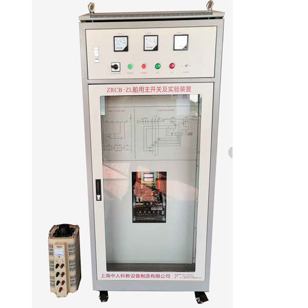
This device is developed for teaching and tr*ning assessment of marine electrical and marine engineering majors in various maritime vocational schools , social shipbuilding and rep*r units, and crew tr*ning institutions . It is suitable for classroom demonstrations, operation of ship m*n switches, and tr*ning practices.
2. Product Features
1. The panel is printed with the m*n switch control electromagnetic closing principle diagram and tripping diagram
2. Equipped with voltmeter and ammeter to indicate three-phase voltage and current
3. Equipped with remote control opening and closing buttons and opening and closing indicator lights
3. Technical performance
1. Input power: AC380V±10% 50Hz
2. Working environment: temperature -10℃~+40℃, relative humidity <85% (25℃), altitude <4000m
3. Device capacity: <1.5kVA
4. Dimensions: 700mm×600mm×1700mm
4. Device composition and configuration
1. Power switch
The m*n power supply of the cabinet is controlled by an *r switch with leakage protection. A fan is installed on the top of the cabinet. When the temperature inside the cabinet is too high, the fan is turned on to dissipate heat for the control cabinet.
2. Operation electrical circuit diagram
The panel is printed with the m*n circuit control circuit electromagnetic closing principle diagram and tripping schematic diagram, which can intuitively show the working principle of the DW95 control circuit.
3. Circuit breaker control circuit test instrument area
The panel is equipped with a voltmeter and a band switch for indicating the three-phase voltage, and three ammeters for indicating the three-phase current. These components are directly installed on the panel surface.
The panel is also equipped with working indicator lights and operation buttons for indicating and controlling the status of the circuit breaker.
4. Marine universal *r circuit breaker
Adopts real components of CDM1 series, which is in line with actual on-site operation tr*ning.
5. Auto-voltage regulator
The system is equipped with an autovoltage regulator to simulate undervoltage and loss of grid voltage, causing the circuit breaker protection device to operate.
6. Fault setting and troubleshooting box
The fault can be set arbitrarily by the fault setting switch in the box, and the fault can be corrected by the troubleshooting button on the box panel. The fault indicator light is used to indicate the fault correction status, and a counter is provided to display the number of troubleshooting times.
7. Teaching software
1. Electrical safety and electric shock first *d simulation teaching software
The software uses a combination of two-dimensional and three-dimensional virtual images to teach students the safety and first *d methods of electricity use. The software has single-phase electric shock, two-phase electric shock, step electric shock, low-voltage electric shock first *d, high-voltage electric shock first *d, artificial respiration rescue method, hand-holding breathing rescue method, chest cardiac compression rescue method and other principle explanations and teaching. Single-phase electric shock is divided into m*ntenance of live disconnection, m*ntenance of socket electric shock, outdoor electric shock and other principle demonstrations. Low-voltage electric shock and high-voltage electric shock teaching m*nly expl*n and demonstrate to students how to rescue people in low-voltage electric shock or high-voltage electric shock. Artificial respiration rescue method, hand-holding breathing rescue method, chest cardiac compression rescue method are displayed using 3D virtual simulation technology. After rendering and polishing, the model looks the same as the real part and the picture is realistic. Through practical tr*ning, students can be educated on safe use of electricity in the tr*ning room, improve their safety awareness, learn some self-rescue methods, and take cert*n safety measures to protect themselves when they encounter danger, as well as be familiar with the causes of various electrical accidents and practical operational measures for handling electrical accidents, so as to reduce the occurrence of electrical accidents.
2. M*ntenance of electrical and electronic machinery and professional qualification tr*ning and assessment simulation software
This software is in apk format and can be used on PC or mobile. This software can set faults manually or automatically. This software can select the manual setting of fault points through the green box in the circuit diagram (up to 39 fault points can be set), or the system can automatically set one fault point at random, two fault points at random, three fault points at random, four fault points at random, and five fault points at random. This software has toolbox, component library, magnifying glass, circuit diagram and other functions. You can select a multimeter for detection through the toolbox, select appropriate components through the component library, and use a magnifying glass to clearly understand each component and circuit. This software sets the fault of the motor star-delta starting control circuit and, after various investigations, allows students to understand the working principle and circuit structure of the motor star-delta starting control circuit.
3. Virtual spectrum analyzer, logic analyzer, oscilloscope, three-meter simulation software:
This software is in apk format and can be used on PC or mobile. The functions of this software include: resistance measurement, AC voltage measurement (measuring transformers, if the transformer burns out the multimeter, black smoke will be emitted and the multimeter can be reset), transistor polarity judgment, DC voltage measurement (the light is on when the ammeter is turned on), DC current measurement, and judgment of the quality of capacitors. This software can drag the red and black pen heads at will. When the two pen heads are dragged to the measured object for positioning, a red circle will be displayed. If the positioning is not accurate, no red circle will be displayed. When an incorrect operation is performed (such as the selected range is wrong, the measured data is wrong, etc.), the instrument pointer will not respond, prompting an error to re-measure, etc. This multimeter can select AC voltage, DC voltage, resistance, current, resistance adjustment 0, and can enlarge the displayed data, so that the size of the measured data can be clearly viewed. Students can learn the correct use of multimeters through this software.
4. Single chip microcomputer , PLC programmable design and control virtual simulation software:
This software is developed based on unity3d, and has built-in experimental steps, experimental instructions, circuit diagrams, component lists, connection lines, power on, circuit diagrams, scene reset, return and other buttons. After the connection and code are correct, the 3D machine tool model can be operated through the start/stop, forward motion, and reverse motion buttons. When the line is connected, the 3D machine tool model can be enlarged/reduced and translated.
1. Relay control: Read the experiment instruction manual and enter the experiment. By reading the circuit diagram, select relays, thermal relays, switches and other components in the component list and drag them to the electrical cabinet. Place the limiter on the 3D machine tool model. You can choose to cover the lid. Some component names can be renamed. Then click the connect line button to connect the terminals. After the machine tool circuit is successfully connected, choose to turn on the power and operate. If the component or line connection is wrong, an error box will pop up and the scene can be reset at any time.
2.PLC control: The experiment is the same as relay control, with the addition of PLC control function. After the connection is completed, press the PLC coding button to enter the program writing interface, write two programs, forward and reverse, with a total of 12 ladder diagram symbols. After writing, select Submit for program verification. After successful verification, turn on the power to operate. Error boxes will pop up for components, line connections, and code errors, and the scene can be reset at any time.
3. Single-chip microcomputer control: The experiment is the same as relay control, with the addition of single-chip microcomputer control function. After the connection is completed, enter the programming interface through the C coding button, enter the correct C language code, submit and verify successfully, turn on the power to operate, and a prompt error box will pop up for component, line connection, and code errors, and the scene can be reset at any time.
5. Tr*ning Project
1. Understand the working principle of universal circuit breaker
2. Opening and closing operation of marine universal circuit breaker
3. Marine universal circuit breaker protection operation
欢迎咨询YLCB-ZL Ship main switch experimental device相关问题,我们是源头工厂,有标准工业厂房生产基地,欢迎前来考察,如有YLCB-ZL Ship main switch experimental device其他问题,可联系19957812178