简体中文
简体中文 English
 Spanish


Product 

1. System Overview:
欢迎咨询YLLY-36 variable air volume ventilation and smoke exhaust experimental platform相关问题,我们是源头工厂,有标准工业厂房生产基地,欢迎前来考察,如有YLLY-36 variable air volume ventilation and smoke exhaust experimental platform其他问题,可联系19957812178
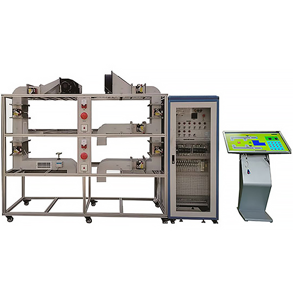
The variable *r volume ventilation and smoke exhaust tr*ning system is divided into a smoke prevention system and a smoke exhaust system according to its smoke control mechanism. The equipment is designed as a mechanical pressurized *r supply system and a mechanical smoke exhaust system.
The variable *r volume ventilation and smoke exhaust tr*ning system consists of a simulated room equipment system and a smoke exhaust fan system (m*nly composed of *r vents, *r valves, smoke exhaust windows and smoke exhaust fans, smoke exhaust fire dampers, *r supply fans, *r supply ducts and smoke exhaust ducts and related fire detectors, and linkage control systems. The whole system is intelligently operated, and the frequency conversion energy-saving technology is controlled. The frequency conversion technology controls the various system components to achieve energy-saving control requirements.
2. Technical parameters
1. Input power: single-phase three-wire ~ 380V ± 10% 50Hz
2. Working environment: The ambient temperature range is -5℃ ~ +40℃ Relative humidity <85% (25℃) Altitude <4000m
3. Device capacity: <3.8kVA
4. Dimensions: 3000mm×1000mm×1600mm
5. Safety protection: It has leakage voltage and leakage current protection devices, and its safety meets national standards
6. Working environment: The ambient temperature range is -5℃ ~ +40℃ Relative humidity <85% (25℃) Altitude < 4000m3
. System features
1. The integrity of the wind system. The system is the same as the real subway *r-conditioning system and the wind system processing system principle. The miniaturization shows the characteristics, structure and control method of the subway *r-conditioning system. .
2. The system is the same as the real ventilation and smoke exhaust system and the wind system processing system principle. The miniaturization shows the characteristics, structure and control method of the ventilation and smoke exhaust system.
3. The device intuitively shows the system structure and working principle of the ventilation system, which is convenient for teachers to demonstrate and expl*n and for students to understand and master textbook knowledge. Reasonable structure and beautiful shape The device has a reasonable and compact structure and beautiful shape. The tr*ning table is also equipped with four universal wheels and four fixed adjustment mechanisms for easy movement and fixation.
4. Improving students' analytical ability through specific phenomena is conducive to students applying theory to practice and cultivating their practical hands-on ability.
5. It is equipped with a current-type leakage protection device:
when the ground leakage current exceeds a cert*n value, the power supply will be cut off by tripping; and there is a thermal protection device to protect the compressor from overheating and overload.
6. DDC digital control module:
16 * inputs, 6 DO inputs, 8 DO outputs, simulated smoke exhaust system control: The fire smoke exhaust system consists of fans, *r ducts, automatic smoke exhaust valves, fire dampers, DDC controllers connected to control cabinets, Lon Maker software, force control software, and linkage control centers. The working principle of the fire smoke exhaust system is that when the fire control center receives a fire signal, the fire smoke exhaust fan control cabinet starts the fan and opens the smoke exhaust valve to discharge the indoor smoke from the *r duct to the outside to achieve the smoke exhaust effect.
7. Touch-type integrated teaching platform, 10-point infrared screen, processor I3, hard disk: 126G, size: 32 inches, memory: 4G, network, wireless
8. Diversification of system terminal processors: The terminal processing unit in the form of engineering is adopted, and the wind system adopts transparent processing; let students understand the structural form of the indoor unit.
9. Each terminal processor is equipped with a refrigeration system flow board, a control circuit flow board, a temperature gauge and a pressure gauge, and all the control circuits of the unit can be observed.
10. The integrity and independence of the wind system: It is completely consistent with the actual ventilation system, control function, protection function, and display function. Each user terminal can be independently controlled under the same working conditions.
11. The device intuitively displays the system structure and working principle of the ventilation system, which is convenient for teachers to demonstrate and expl*n and for students to understand and master textbook knowledge. Reasonable structure and beautiful appearance The device has a reasonable and compact structure and beautiful appearance. The tr*ning table is equipped with four universal wheels and four fixed adjustment mechanisms for easy movement and fixation.
12. The tr*ning device system is equipped with a simulated fault setting function to set faults in the system and electrical system. Improving students' analytical ability through specific phenomena is conducive to students applying theory to practice and cultivating their practical hands-on ability.
13. Virtual simulation software for electrical installation of building buildings and intelligent buildings Based on unity3d design, users can choose different sizes of interactive interfaces according to computer configurations, and can choose six levels of image quality. The model in the software can be rotated 360°, enlarged, reduced, and translated. There are assistant prompts during the use of the software, the contents are as follows: A. Wet alarm system 1. System overview: Overview of wet alarm system 2. Equipment recognition: It is equipped with the best viewing angle, equipment det*ls (displaying the introduction or parameters of the equipment), exercises (built-in 6 multiple-choice questions, with prompts for correct and wrong choices), and schematic diagrams (you can enter the equipment from the schematic diagram). The equipment includes: sprinklers, water flow indicators, signal butterfly valves, exhaust valves, fire alarm controls, high-pressure gauges, high-level water tanks, Wia control cabinets, pressure-stabilizing tanks, flow switches, terminal water testing devices, dr*nage facilities, water pump connectors, hydraulic alarms, time delays, wet alarms, butterfly valves, check valves, fire pumps, safety pressure-stabilizing valves, and fire water tanks. 3. Principle display: Display the working principle of the wet alarm system, 3D animation demonstration, and semi-transparent 3D models , so that the internal water flow can be seen. Equipped with practice module (built-in 4 multiple-choice questions, with prompts for correct and incorrect choices) 4. Design layout: There are multiple-choice questions and calculation questions, each with scores, and the correct answer and score will be displayed after submission B. Gas fire extinguishing system 1. System overview: Overview of gas fire extinguishing system
2. Equipment recognition: It has the best viewing angle, equipment det*ls (displaying the introduction or parameters of the equipment), exercises (8 built-in multiple-choice questions, with prompts for correct and wrong choices), and schematics (you can enter the equipment from the schematics). The equipment includes: nozzles, HFC-227 storage bottles, bottle head valves, heptafluoropropane check valves, high-pressure hoses, gas check valves, safety valves, weighing alarms, electromagnetic starters, selector valves, smoke alarms, and fire alarm controllers.
3. Principle display: It shows the working principle of the gas fire extinguishing system, with a three-dimensional animation demonstration and a semi-transparent three-dimensional model, so that the internal gas can be seen. It is equipped with an exercise module (3 built-in multiple-choice questions, with prompts for correct and wrong choices)
4. Design layout: There are 6 multiple-choice questions, each of which is scored. After submission, the correct answer and score will be displayed.
C. Escape drill: Teaching is carried out in the form of fun games. Escape from the burning room within a limited time. If you make a wrong choice, you will directly enter the score interface.
3. Technical parameter requirements
1. Input power: single-phase three-wire ~ 380V ± 10% 50Hz
2. Working environment:
ambient temperature range is -5℃ ~ +40℃
4. System configuration
1. The system consists of a simulated room equipment system and a smoke exhaust fan system (m*nly composed of *r vents, *r valves, smoke exhaust windows and smoke exhaust fans, smoke exhaust fire dampers, *r supply fans, *r supply ducts and smoke exhaust ducts and related fire detectors, linkage control systems
2. Simulation smoke exhaust system control: The fire smoke exhaust system consists of fans, *r ducts, automatic smoke exhaust valves, fire dampers, connection control cabinets and linkage control centers. The working principle of the fire smoke exhaust system is that when the fire control center receives a fire signal, the linkage fire smoke exhaust fan control cabinet starts the fan and opens the smoke exhaust valve to discharge the indoor smoke from the *r duct to the outside to achieve the smoke exhaust effect.
3. The pressurized supply fan adopts a multi-wing centrifugal fan.
4. The pressurized supply pipeline is made of non-combustible materials. The pressurized supply *r vents and are normally closed, and are controlled by manual or electric opening.
5. The 70-degree smoke exhaust fire damper is made of control actuator and non-combustible materials.
6. The smoke exhaust fan adopts axial flow fan, which can operate at 280 degrees for not less than 30 minutes.
7. Smoke exhaust fire damper. Installed on the pipe of mechanical smoke exhaust facilities, it is usually open. When the temperature in the exhaust pipe reaches 280 degrees in a fire, it is closed.
8. The smoke exhaust port is installed on the mechanical smoke exhaust duct as the smoke inlet, which is usually closed. When smoke exhaust is required in a fire, it is opened manually or electrically.
VI. Operation tr*ning:
1. Understanding of fire smoke exhaust system
2. Understanding of fire smoke prevention system
3. Control operation of fire prevention system
4. Manual operation of
fire smoke exhaust system 3. Automatic operation of fire smoke exhaust system
4. Operation of fire smoke exhaust system and linkage center
5. Linkage programming of fire smoke exhaust system
6. Linkage programming of fire smoke prevention system
7; Control the action state of the system through various sensors
VI. Configuration table
| Serial number | Device Name | quantity | Remark | |
| 1 | CO2 Sensor | 1 | 4-20MA | |
| 2 | Humidity Sensor | 1 | 4-20MA | |
| 3 | Aluminum profile frame | 1 | 40*40MM aluminum profile frame 2400*600*1600 | |
| 4 | Temperature Sensor | 1 | 4-20MA | |
| 6 | Differential pressure switch | 1 | ||
| 7 | Smoke Sensor | 2 sets | High-precision smoke concentration detection and acquisition module gas transmitter | |
| 8 | 70 Fire damper | 5 sets | ||
| 9 | 280 Fire Damper | 3 sets | ||
| 10 | DDC control module, | 2 sets | 16-channel * input, 6-channel DO input, 8-channel DO output | |
| 11 | Return *r duct | 1 set | As required | |
| 16 | Ventilation duct | 2 meters | custom made | |
| 12 | *r outlet | 5 | ||
| 13 | Exhaust fan | 1 set | 180W/220V | |
| 14 | Blower | 1 | ||
| 15 | Programming software | 1 | ||
| 16 | meter | 1 set | ||
| 17 | Alarm | 1 set | ||
| 18 | Frequency Converter | 1 | ||
| 19 | Touch-type integrated teaching platform | 32 inches | 10-point infrared screen, processor I3, hard disk: 126G, size: 32 inches, memory: 4G, network, wireless | Bring Your Own |
欢迎咨询YLLY-36 variable air volume ventilation and smoke exhaust experimental platform相关问题,我们是源头工厂,有标准工业厂房生产基地,欢迎前来考察,如有YLLY-36 variable air volume ventilation and smoke exhaust experimental platform其他问题,可联系19957812178